
Coating composition for the formation of low refractive index layer, antireflection film, polarizing plate and liquid crystal display device

a technology of coating composition and low refractive index, applied in anti-reflective coatings, instruments, transportation and packaging, etc., can solve the problems of insufficient anti-fouling property, deterioration of scratch resistance and anti-fouling properties, and impaired film strength and adhesion to the lower layer. , to achieve the effect of low refractive index, excellent scratch resistance and anti-fouling properties, and low reflectivity

Active Publication Date: 2008-09-02
FUJIFILM CORP
View PDF5 Cites 15 Cited by
  • Summary
  • Abstract
  • Description
  • Claims
  • Application Information

AI Technical Summary

Benefits of technology

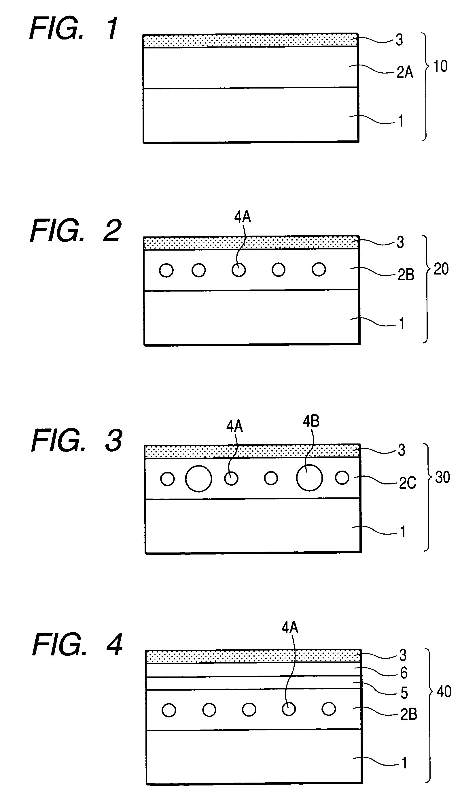
The present invention provides a coating composition for forming a low refractive index layer that has excellent scratch resistance and antifouling properties, even at low reflectivity. The coating composition includes a fluorine-containing olefin-based polymer and a hollow silica fine particle. The invention also provides an antireflection film that includes a transparent support, at least one hard coat layer, and a low refractive index layer formed by curing the coating composition. The hard coat layer can be made with a hydrolysate of an organosilane or a metal chelate compound. The antireflection film has low surface roughness and high transmitted image clarity. The invention also provides a method for improving the scratch resistance and antifouling properties of a low refractive index layer by adding a specific compound to the coating composition.

Problems solved by technology

However, in any attempt, there is caused a problem that the film strength and adhesion to the lower layer are impaired and the scratch resistance is deteriorated.
In these cases, a certain effect of improvement is obtained with respect to the projection of outside light and the scratch resistance, but the antifouling property is insufficient and an antifouling layer must be further provided on the low refractive index layer.

Method used


Image

  • Coating composition for the formation of low refractive index layer, antireflection film, polarizing plate and liquid crystal display device
  • Coating composition for the formation of low refractive index layer, antireflection film, polarizing plate and liquid crystal display device
  • Coating composition for the formation of low refractive index layer, antireflection film, polarizing plate and liquid crystal display device

Examples


examples

[0502]The present invention is described in greater detail below by referring to Examples, but the present invention is limited thereto.

[0503]In the present invention, the “parts” denotes “parts by mass”.

(Synthesis of Fluorine-Containing Olefin-Based Polymer A)

[0504]A stainless steel-made autoclave equipped with a magnetic stirrer having an internal volume of 1.5 liter was thoroughly replaced by a nitrogen gas and thereinto, 600 g of ethyl acetate, 91.5 g of perfluoro(propyl vinyl ether) (FPVE), 57.9 g of ethyl vinyl ether (EVE), 30.3 g of 2-hydroxy ethyl vinyl ether (HEVE), 60.0 g of nonionic reactive emulsifier “ADEKA REASOAP NE-30” (produced by Asahi Denka Kogyo Co., Ltd.), 5.0 g of azo group-containing polydimethylsiloxane “VPS-1001” (produced by Wako Pure Chemicals Industries, Ltd.), and 1.5 g of dilauroyl peroxide (LPO) were charged. After cooling to −50° C. with dry ice-methanol, oxygen in the system was removed again by a nitrogen gas. Subsequently, 144.4 g of hexafluoroprop...


PUM

PropertyMeasurementUnit
particle diameteraaaaaaaaaa
refractive indexaaaaaaaaaa
roughnessaaaaaaaaaa

Abstract

A coating composition for the formation of a low refractive index layer, comprising: a fluorine-containing olefin-based polymer that has a polysiloxane segment represented by formula 1 in its main chain, has a fluorine content of 30 mass % or more, and contains a plurality of ethylenically unsaturated groups; and a hollow silica fine particle having an average particle diameter of 5 to 200 nm and a refractive index of 1.17 to 1.40: Formula 1:[wherein R1 and R2, which may be the same or different, each represents a hydrogen atom, an alkyl group, an alkyl halide group or an aryl group].

Description

BACKGROUND OF THE INVENTION[0001]1. Field of the Invention[0002]The present invention relates to a coating composition capable of forming a low refractive index layer excellent in the scratch resistance and antifouling property, and a display device used for the image display of a computer, a word processor, a television and the like. More specifically, the present invention relates to an antireflection film, a polarizing plate and a liquid crystal display device, which are effective for enhancing the display quality.[0003]2. Description of the Related Art[0004]In a display device such as cathode ray tube display device (CRT), plasma display panel (PDP), electroluminescence display (ELD) and liquid crystal display device (LCD), an antireflection film is generally disposed on the outermost surface of a display for preventing reduction in contrast or projection of an image due to reflection of outside light and enhancing the visibility of an image by utilizing the principle of light d...

Claims


Application Information

Patent Timeline
Patent Type & Authority Patents(United States)
IPC IPC(8): C09K19/00C09K19/52
CPCC09D7/1266C09D7/1275C09D7/1291G02B1/111G02F1/133502C09D183/04C08K3/36C08K7/26C08K9/06Y10T428/10C09K2019/0429G02F2201/50Y10T428/1041C09D7/67C09D7/68C09D7/70Y10T428/31663C09D7/62C09D5/006C09K2323/031C09K2323/00
Inventor ANDO, TAKUMIFUKUSHIGE, YUUICHI
Owner FUJIFILM CORP
Learn More