High-efficiency enhanced boiler
a boiler and high-efficiency technology, applied in the field of heat exchangers, can solve the problems of large and more expensive devices, and achieve the effects of enhancing convection/conduction couples, enhancing heat transfer relationships, and increasing the surface area involved in heat transfer relationships
- Summary
- Abstract
- Description
- Claims
- Application Information
AI Technical Summary
Benefits of technology
Problems solved by technology
Method used
Image
Examples
example 1
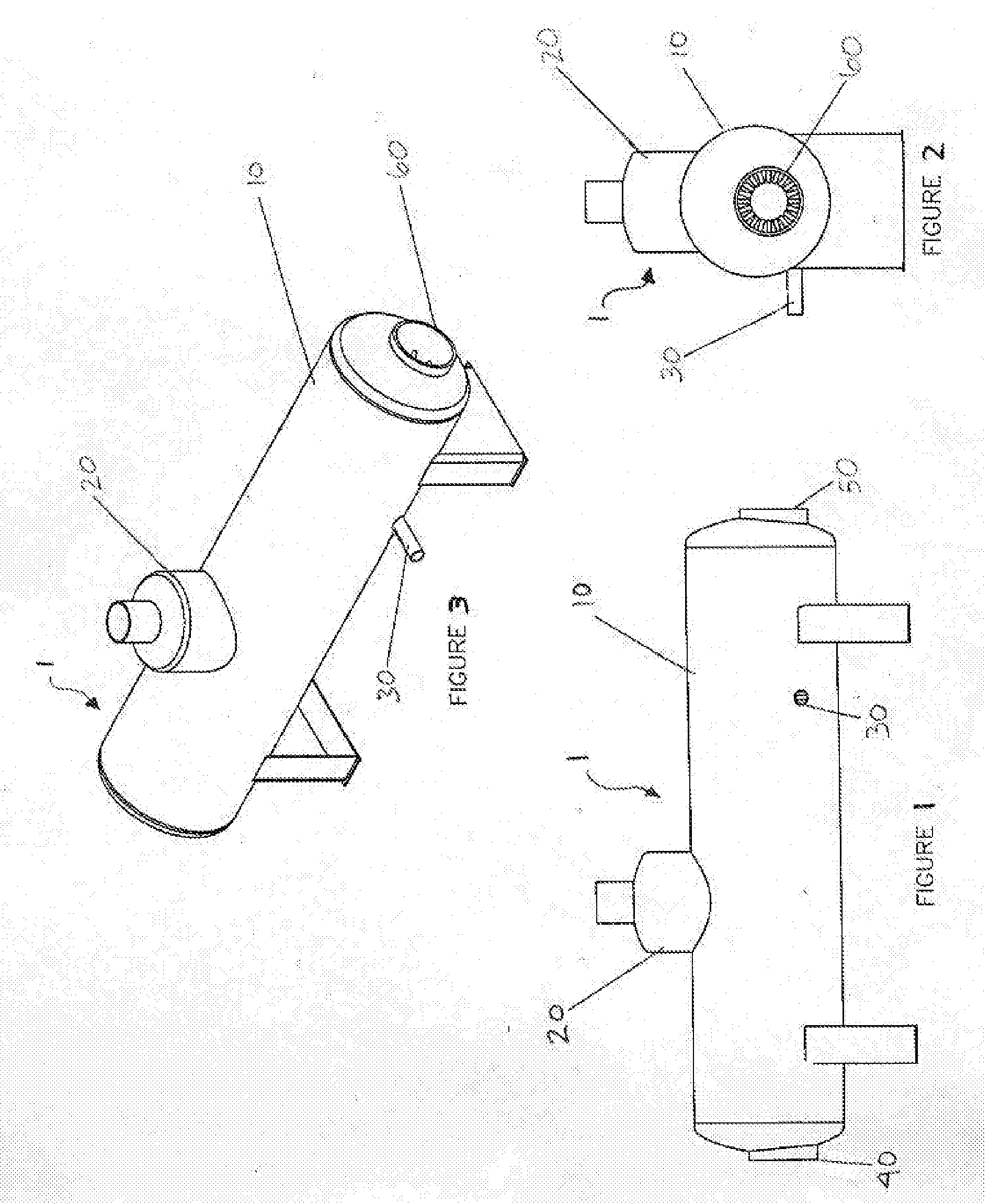
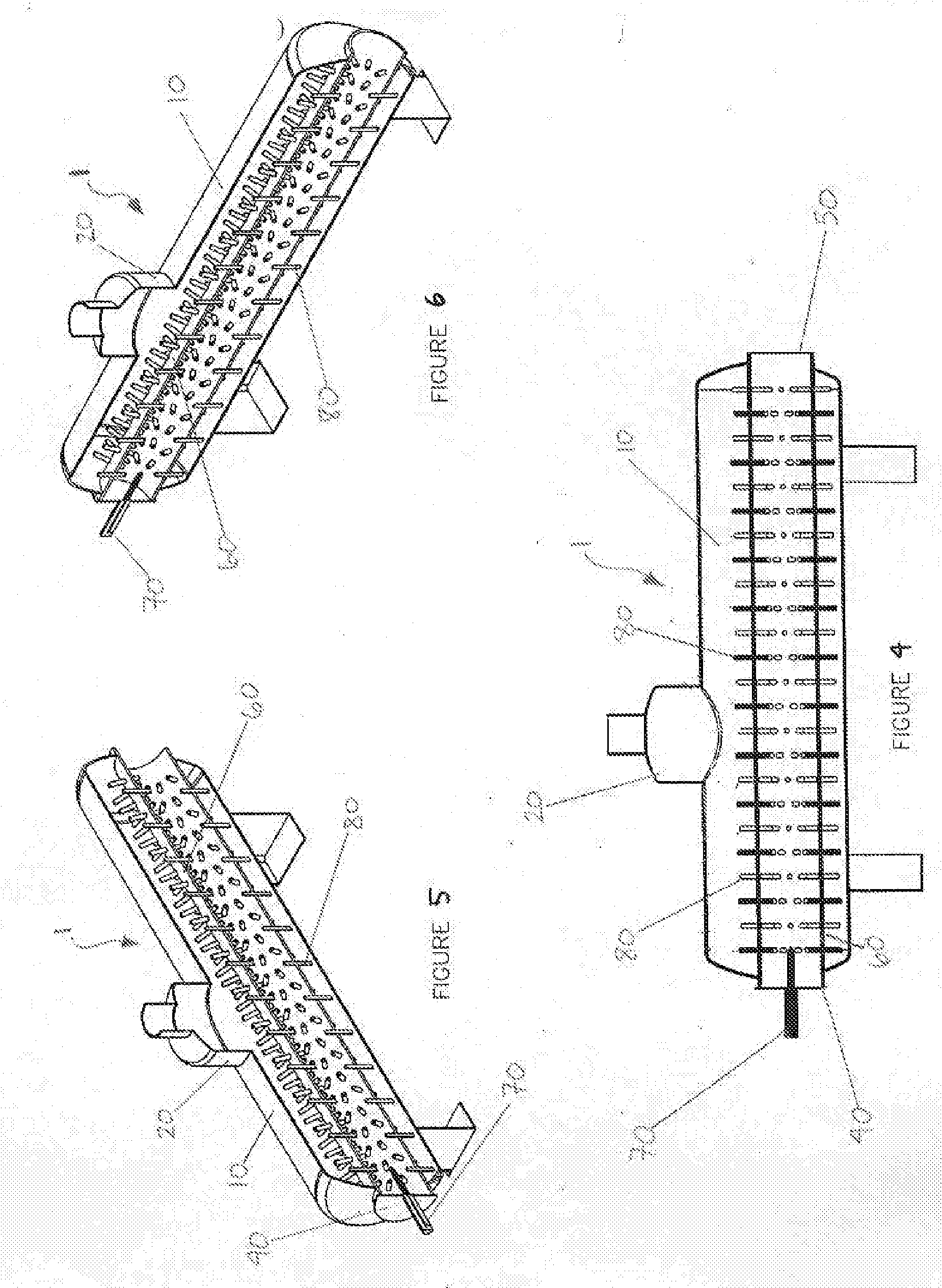
[0052]Referring to FIGS. 7-12, a direct-fired 3-pass 30-horsepower boiler 100 is shown, fabricated in accordance with the present design criteria for a pressure of 10 atmospheres and requiring a one million BTU (British thermal units) natural gas burner. Cylindrical vessel 110 has dimensions of 42-inches O.D. wide by 60-inches O.D. long, with ten-inch diameter enhanced conduit 160 winding through the interior of the vessel. Hot fluid enters boiler 100 through hot fluid inlet 140, passes through enhanced conduit 160, and exits through flue outlet 150. Condensate returns to boiler 100 through feedwater inlet 130. There are 280 ¾″ diameter fins 180 located circumferentially throughout enhanced conduit 160 in sets of ten. Fins 180 are mechanically fastened to enhanced conduit 160 by virtue of a self-locking taper and seal welding. The temperature of the exhausted flue gas is approximately 230° C. The thermal efficiency of such a design is increased, in part, due to the fact that “turn-a...
example 2
[0053]Referring now to FIGS. 13-18, a direct-fired boiler 200 is shown with a coiled enhanced conduit 260. The long axis of cylindrical vessel 210 is oriented vertically, rather than horizontally as in Example 1. Rather than completing a series of reversals in direction as in Example 1, enhanced conduit 260 is coiled within vessel 210, completing a total of three revolutions. Hot fluid enters boiler 200 through hot fluid inlet 240, passes through enhanced conduit 260, and exits through flue outlet 250. As in Example 1, enhanced conduit 260 contains a plurality of fins 280 located around its circumference and along its length. Fins 280 may be fastened to enhanced conduit 260 by any of a number of means described above.
example 3
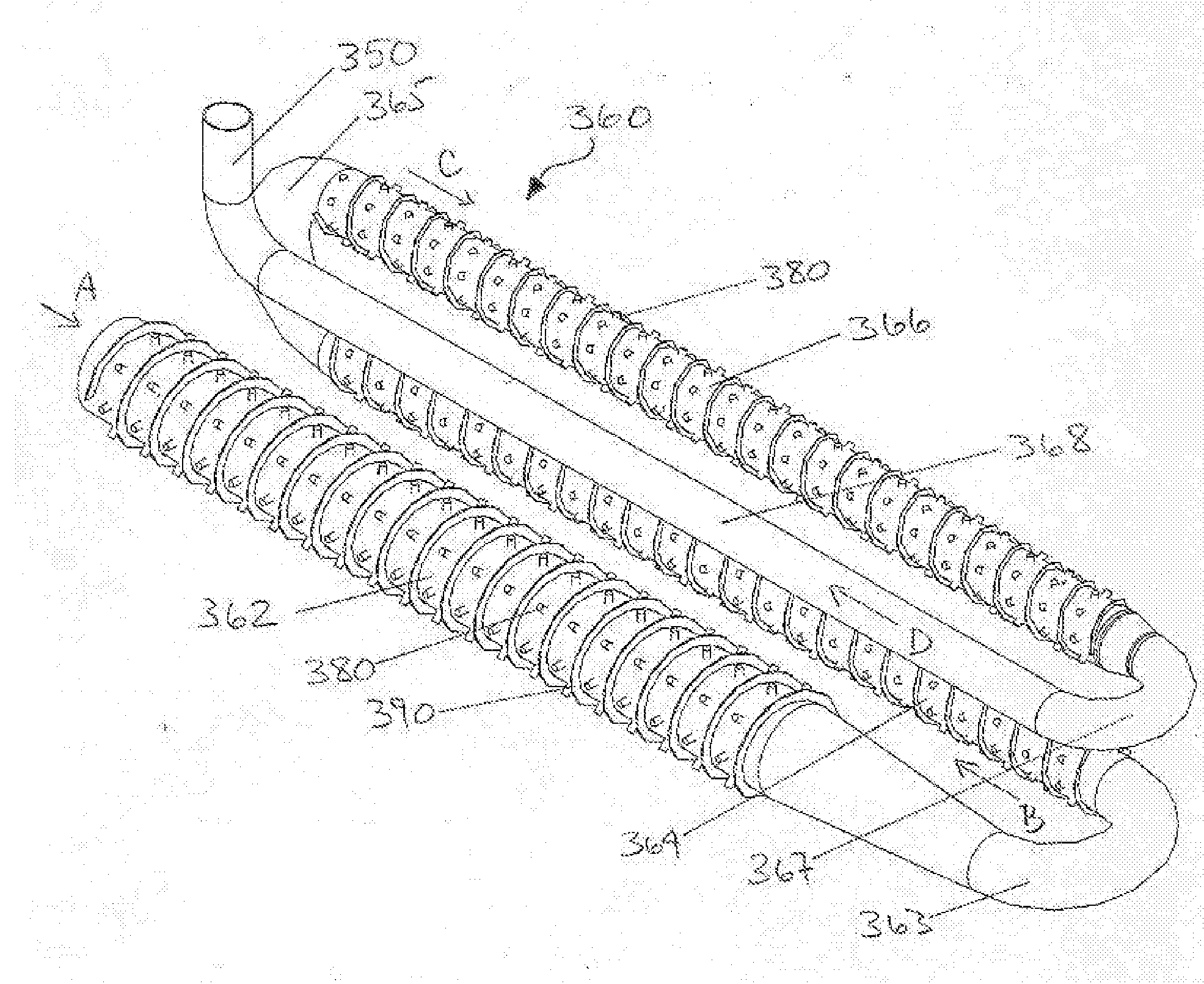
[0054]Referring to FIGS. 19-21, a 4-pass conduit 360 is shown. Unlike earlier-described embodiments, wherein a heat transfer medium sits within a vessel, the depicted embodiment incorporates a housing 360A around the apparatus 360. Housing 360A directs a heat transfer medium along an outer surface of a pass 362, 364, 366, 368 as the hot fluid is directed along an inner surface of the same pass. In some embodiments, such as that shown in FIG. 20, the apparatus has a “reverse flow,” wherein as the hot fluid enters first pass 362 (often a firetube), the heat transfer medium enters through a heat transfer medium inlet 368B at a distal end of the fourth pass housing 368A, flows in a direction substantially opposite that of the hot fluid, and exits through a heat transfer medium outlet 362B at a proximal end of the first pass housing 362A.
[0055]In the embodiment depicted in FIG. 19, three of the four passes 362, 364, 366 are enhanced, each containing a plurality of fins 380 extending thro...
PUM
 Abstract
Description
Claims
Application Information
 - R&D
- Intellectual Property
- Life Sciences
- Materials
- Tech Scout
- Unparalleled Data Quality
- Higher Quality Content
- 60% Fewer Hallucinations
Browse by: Latest US Patents, China's latest patents, Technical Efficacy Thesaurus, Application Domain, Technology Topic, Popular Technical Reports.
© 2025 PatSnap. All rights reserved.Legal|Privacy policy|Modern Slavery Act Transparency Statement|Sitemap|About US| Contact US: help@patsnap.com


