Image-taking apparatus

a technology of image-taking apparatus and in-focus position search, which is applied in the field of image-taking apparatus, can solve the problems of unfavorable natural focus changes, requiring a longer time period to achieve focusing, and high focusing accuracy, so as to reduce minimize the occurrence of unnatural focus changes. , the effect of reducing the time to achieve focusing

Inactive Publication Date: 2008-07-22
CANON KK
View PDF8 Cites 13 Cited by
  • Summary
  • Abstract
  • Description
  • Claims
  • Application Information

AI Technical Summary

Benefits of technology

[0012]It is an object of the present invention to provide an image-taking apparatus which achieves higher accuracy of an in-focus position search in the TV-AF method to reduce the time to achieve focusing, thereby minimizing occurrence of unnatural focus changes as mentioned above, a focus control method, and a focus control processing program for the image-taking apparatus.

Problems solved by technology

While the TV-AF method generally allows more accurate focusing than the other AF methods, the TV-AF method has the higher focusing accuracy and accordingly tends to require a longer time period to achieve focusing than the other AF methods.
Also, when an object is taken with low contrast or in dark conditions, searching for an in-focus position is not necessarily performed accurately in the TV-AF method.
If the search for an in-focus position is performed in a wrong direction in which a true in-focus position does not exist, it takes a long time to achieve focusing.

Method used


Image

  • Image-taking apparatus
  • Image-taking apparatus
  • Image-taking apparatus

Examples


embodiment 1

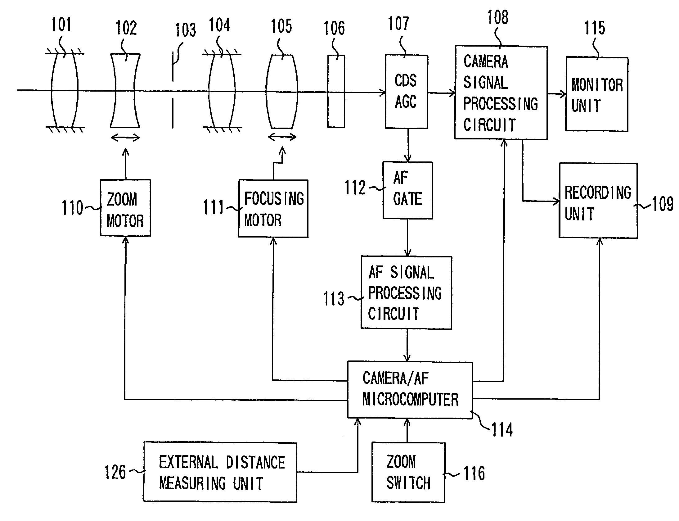
[0048]FIG. 1 shows the structure of a video camera (an image-taking apparatus) which is Embodiment 1 of the present invention. While description is made for a video camera integral with an image-taking lens, the present invention is applicable to a video camera on which an image-taking lens is mountable. In this case, a control signal produced by a camera / AF microcomputer, later described, is communicated to a microcomputer in the image-taking lens such that the camera / AF microcomputer controls the drive of a focus lens unit via the lens microcomputer. In addition, while the video camera is described in Embodiment 1, the present invention is applicable to various types of image-taking apparatuses such as a digital still camera. This applies to Embodiment 2, later described.

[0049]In FIG. 1, reference numeral 101 denotes a first fixed lens unit, reference numeral 102 denotes a lens unit (hereinafter referred to as a zoom lens unit) which provides variable magnification, reference nume...


PUM


Abstract

An image-taking apparatus is disclosed which achieves focusing in a reduce time with higher accuracy of an in-focus position search in a TV-AF method to minimize occurrence of unnatural focus changes. The image-taking apparatus includes an image-taking element, a first detector which outputs a focus evaluation value signal based on a predetermined frequency component of an output signal of the image-pickup element, a second detector which outputs a detection signal different from the focus evaluation value signal, and a controller which performs first processing of obtaining information for an in-focus position search of the focus lens based on the focus evaluation value signal. The controller performs second processing of obtaining information on an in-focus position based on the detection signal from the second detector, and performs third processing different depending on a comparison result between the information from the first processing and the information obtained from the second processing.

Description

BACKGROUND OF THE INVENTION[0001]1. Field of the Invention[0002]The present invention relates to an image-taking apparatus such as a video camera.[0003]2. Description of the Related Art[0004]In recent years, a so-called TV-AF method is mainly used for auto-focus control in video cameras, in which an object image is photoelectrically converted by an image-pickup element into a video signal from which the sharpness of the video is detected and used as an AF evaluation value, and the position of a focus lens at which the AF evaluation value is at the maximum is searched for.[0005]As the AF evaluation value in the TV-AF method, a high-frequency component extracted from a video signal by a band pass filter for a certain band is typically used. When a normal object image is taken, the AF evaluation value is higher as a focus lens approaches an in-focus point (in-focus position) as shown in FIG. 2. The highest level of the AF evaluation value corresponds to the in-focus point.[0006]Another...

Claims


Application Information

Patent Timeline
Patent Type & Authority Patents(United States)
IPC IPC(8): H04N5/232G03B13/00G03B13/36G02B7/28G02B7/30G02B7/34G02B7/36H04N101/00
CPCH04N5/23212H04N23/673H04N23/60
Inventor YASUDA, HITOSHI
Owner CANON KK
Why Eureka
Try Eureka