
High capacitance cathode foil produced by abrasion process using titanium nitride powder

Inactive Publication Date: 2008-07-22
PACESETTER INC
View PDF14 Cites 23 Cited by
  • Summary
  • Abstract
  • Description
  • Claims
  • Application Information

AI Technical Summary

Benefits of technology

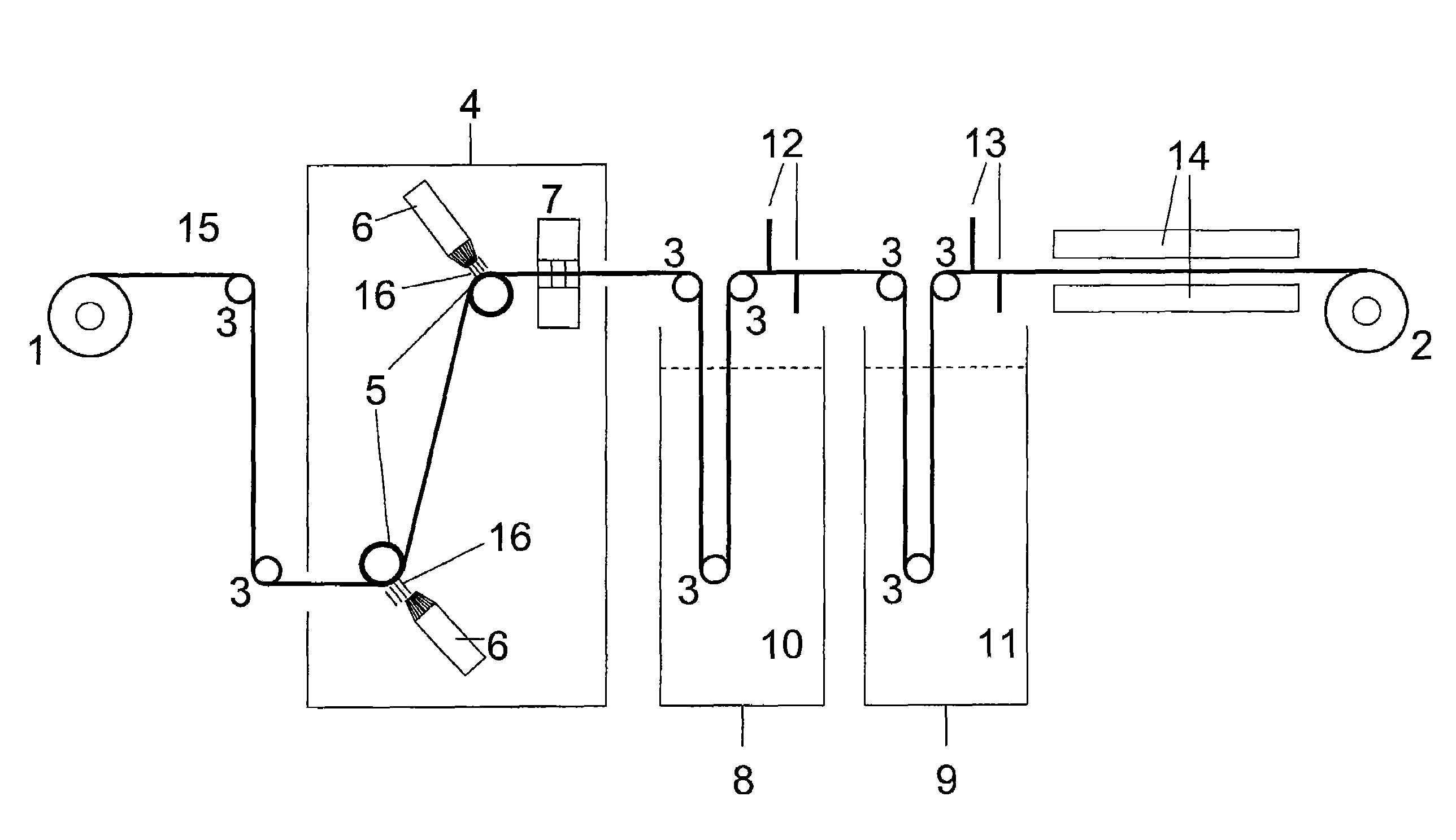
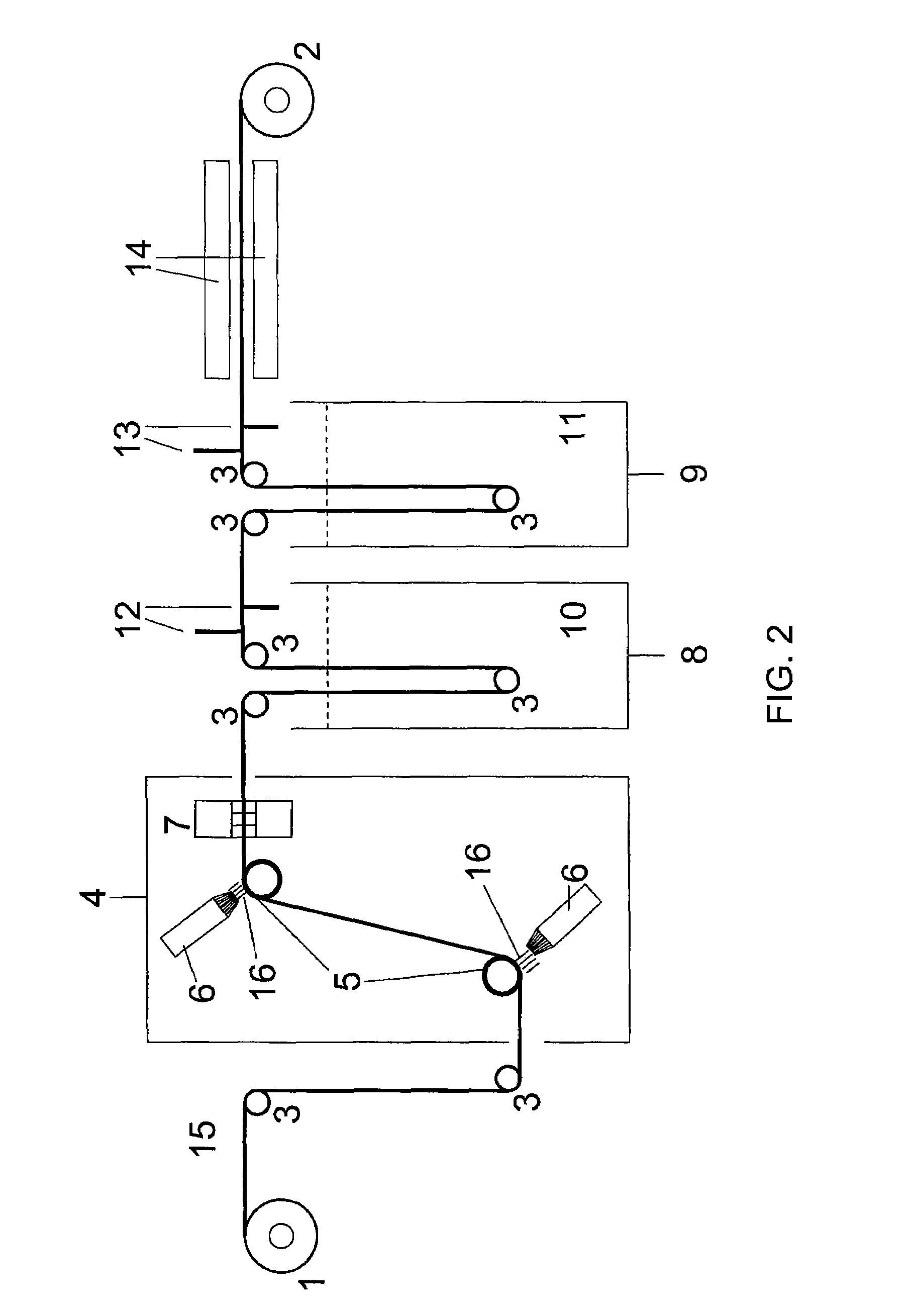
[0011]Another embodiment of the present invention is a method of assembling a flat electrolytic capacitor, comprising the steps of abrading at least one surface of a metal cathode foil with titanium nitride powder, wherein a portion of the titanium nitride powder mechanically alloys with the at least one surface of the metal cathode foil; interleaving the abraded metal cathode foil with a separator material and a poly-anode stack such that a multiple anode stacked capacitor configuration is formed, wherein the separator material prevents electrical contact between the abraded metal cathode and the poly-anode stack; and impregnating the multiple anode stacked capacitor configuration with a solvent-based electrolyte.

Problems solved by technology

However, due to the higher capacitance values achieved with multiple anodes, traditional chemically etched aluminum cathodes provide insufficient capacitance coverage at the desired thickness of 30 microns or less.
Known high capacitance cathode technologies present significant problems.
Etched aluminum cathodes are technologically limited and can not support the high capacitance required when more than two anodes are placed adjacent to each other in a capacitor stack.
Coated cathodes are difficult to obtain commercially and reliably.
Also, known methods of titanium nitride coating are expensive.
Metal oxides are difficult to coat in high purity without chloride contamination.
Conductive polymers have exhibited stability issues under certain loads and uses.

Method used


Image

  • High capacitance cathode foil produced by abrasion process using titanium nitride powder
  • High capacitance cathode foil produced by abrasion process using titanium nitride powder
  • High capacitance cathode foil produced by abrasion process using titanium nitride powder

Examples


example

[0047]Abraded titanium foil with mechanically alloyed TiN powder was manufactured according to the present invention in a lab environment. A piece of 12.5 μm thick titanium foil was taped to a solid metal plate and placed in a 15 gallon bead blasting cabinet. The bead blasting nozzle in the cabinet was filled with 99.95% TiN powder that had been dried in a vacuum oven at 70° C. The bead blasting nozzle was attached to the shop air supply and the pressure was set at 40 psi. The piece of titanium foil was abraded for about 10 seconds, during which the nozzle was moved across the surface of the foil in a helical pattern. After the abrasion process was complete, the titanium foil was removed from the bead blasting cabinet and detached from the solid metal plate.

[0048]The foil was then washed in deionized water. During the wash, the surface of the titanium foil was rubbed with a gloved finger to remove extra TiN powder that remained loosely attached to the surface of the foil. The foil w...


PUM

PropertyMeasurementUnit
Pressureaaaaaaaaaa
Pressureaaaaaaaaaa
Fractionaaaaaaaaaa

Abstract

A dry titanium nitride (TiN) powder abrasion method roughens the surface of a valve metal foil for use as a cathode in an electrolytic capacitor. This increases the surface area of the foil, thereby increasing the double-layer capacitance of the cathode, and also mechanically alloys TiN powder to the surface of the foil, thereby increasing the pseudo-capacitance of the cathode. In one embodiment, a piece of thin titanium foil is mounted on a hard metal backing and at least one surface of the foil is abraded with fine titanium nitride powder. In another embodiment, a continuous metal foil tape is fed into a bead blasting box and at least one surface of the metal foil tape is abraded with TiN powder delivered by a bead blasting nozzle located within the bead blasting box. Accordingly, a cathode having increased capacitance capability is provided to more closely match the capacitance of a poly-anode stack.

Description

BACKGROUND OF THE INVENTION[0001]1. Field of the Invention[0002]The present invention relates to a method for abrading electrodes with titanium nitride powder for use as cathode electrodes of electrolytic capacitors, thereby increasing the capacitance of the cathode foil to more closely match the capacitance of a poly-anode stack.[0003]2. Related Art[0004]Compact, high voltage capacitors are utilized as energy storage reservoirs in many applications, including implantable medical devices. These capacitors are required to have a high energy density since it is desirable to minimize the overall size of the implanted device. This is particularly true of an Implantable Cardioverter Defibrillator (ICD), also referred to as an implantable defibrillator, since the high voltage capacitors used to deliver the defibrillation pulse can occupy as much as one third of the ICD volume.[0005]Implantable Cardioverter Defibrillators, such as those disclosed in U.S. Pat. No. 5,131,388, incorporated he...

Claims


Application Information

Patent Timeline
IPC IPC(8): H01G9/00
CPCH01G9/0425H01G9/055Y10T29/417
Inventor JIANG, XIAOFEI
Owner PACESETTER INC
Learn More