
Nanobiosensor and carbon nanotube thin film transistors

a carbon nanotube and nanotube technology, applied in nanoinformatics, liquid/fluent solid measurement, biomass after-treatment, etc., can solve the problems of limited performance of liquid electrolyte sensors, limited sensitivity and selectivity of conventional sensing electrodes used to immobilize biological enzymes, and limited sensor performan

Inactive Publication Date: 2008-07-15
APPLIED NANOTECH HLDG
View PDF20 Cites 74 Cited by
  • Summary
  • Abstract
  • Description
  • Claims
  • Application Information

AI Technical Summary

Benefits of technology

"The invention is a sensor that uses a carbon nanotube and a polymer to detect a specific substance. The sensing element is attached to the carbon nanotube or the polymer. This design allows for the accurate detection of the analyte and can be used in various applications such as medical diagnostics or environmental monitoring. The technical effect of this invention is the improved sensitivity and accuracy of detecting specific substances."

Problems solved by technology

Conventional sensing electrodes (e.g., gold, platinum, glass, carbon) that have been used to immobilize biological enzymes have shown limited sensitivity and selectivity.
In addition, sensor performance has been limited due to possible interfering compounds.
The performance of the liquid electrolyte sensors are limited by saturation of the analyte in the liquid phase, electrode corrosion and other operation problems including the requirement of continuous stirring to ensure the effective interaction of the analyte with the sensing element.
Aligned carbon nanotubes grown in situ are useful in electrochemical biosensing applications but the difficulties in achieving reproducibility severely limits their use in such applications.
High manufacturing costs associated with producing aligned nanotubes further limit their commercialization.
The “drop and dry” process of the mediator, gel and enzymes did not yield a high sensitive and selective detection.
When optimized, chemical sensors can detect very low levels of a desired analyte, however, the drawback is usually the large amount of support equipment.
This equipment usually prevents the sensors from being portable.
Current methods of detection have limited selectivity when operating at the limits of detection.
At these extremes of performance, separating a signal from the surrounding noise becomes extremely difficult.
These devices are difficult to prepare, requiring tedious placement of electrodes with respect to CNT position.
The use of this instrumentation required for characterization and fabrication prevents this from being a manufacturable technique.

Method used


Image

  • Nanobiosensor and carbon nanotube thin film transistors
  • Nanobiosensor and carbon nanotube thin film transistors
  • Nanobiosensor and carbon nanotube thin film transistors

Examples


example 1

Electrochemical Instrumentation and Materials

[0101]Instrumentation: Experiments using electro-polymerization were carried out using a three electrode Gamry (v. 4.02) electrochemical system coupled to a Gamry Potentiostat (PCI4 / 300). The three electrodes included a working, counter and Ag / AgCl reference. The measurements and analysis were performed and recorded using the Gamry Software (v. 1.02).

[0102]Materials: Single-walled carbon nanotubes (SWNTs) and multi-walled carbon nanotubes (MWNTs) may be purchased from any source. In the CNT-TFT, the SWNTs used have diameters that range from 1 to 3 nm and lengths that range from less than one micron to greater than 10 μm. SWNTs have been used “as-produced” (AP) or purified with similar results. This disclosure does not specify how the carbon nanotubes were made, although methods that deliver higher concentrations of semiconducting nanotubes may be used, either as produced or as a post-fabrication process procedure.

[0103]In the nanobiosenso...

example 2

Preparation of Carbon Nanotube Electrodes

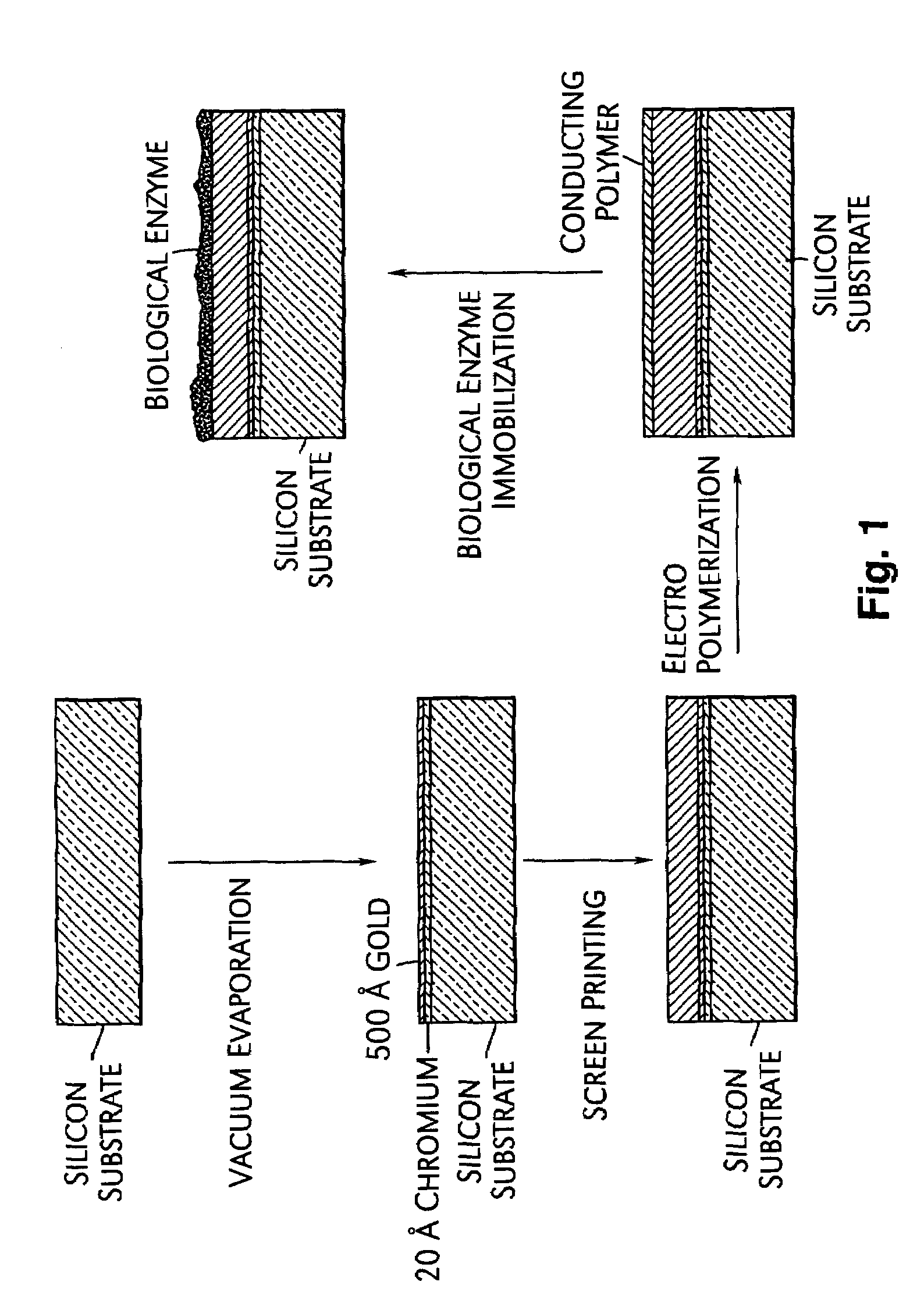
[0104]Carbon nanotube paste electrodes (0.5 cm2) were prepared by mixing 50% by weight of carbon nanotubes with 43% by weight of organic vehicle and 7% by weight of glass frit in a mortar and pestle for 30 minutes followed by grinding in a three roll mill for 20 minutes to disperse the clusters in the mixture. The composite was then screen printed through a mask of known area onto a silicon substrate, vacuum evaporated with 20 angstroms chromium and 500 angstroms gold. The substrate was then baked at 100° C. for 10 minutes in an oven and cooled at room temperature as illustrated in FIG. 1. Different weight percentages of carbon nanotubes can also be employed for the electrode preparation. The prepared carbon nanotube paste electrodes may be fired (hard baked) to remove the organic vehicle and activated using a tape.

[0105]Carbon nanotube spray electrodes (0.5 cm2) were prepared by dissolving a known quantity of carbon nanotubes (e.g., 0.1 g) i...

example 3

Preparation of Carbon Nanotube-conducting Polymer Composite Electrodes

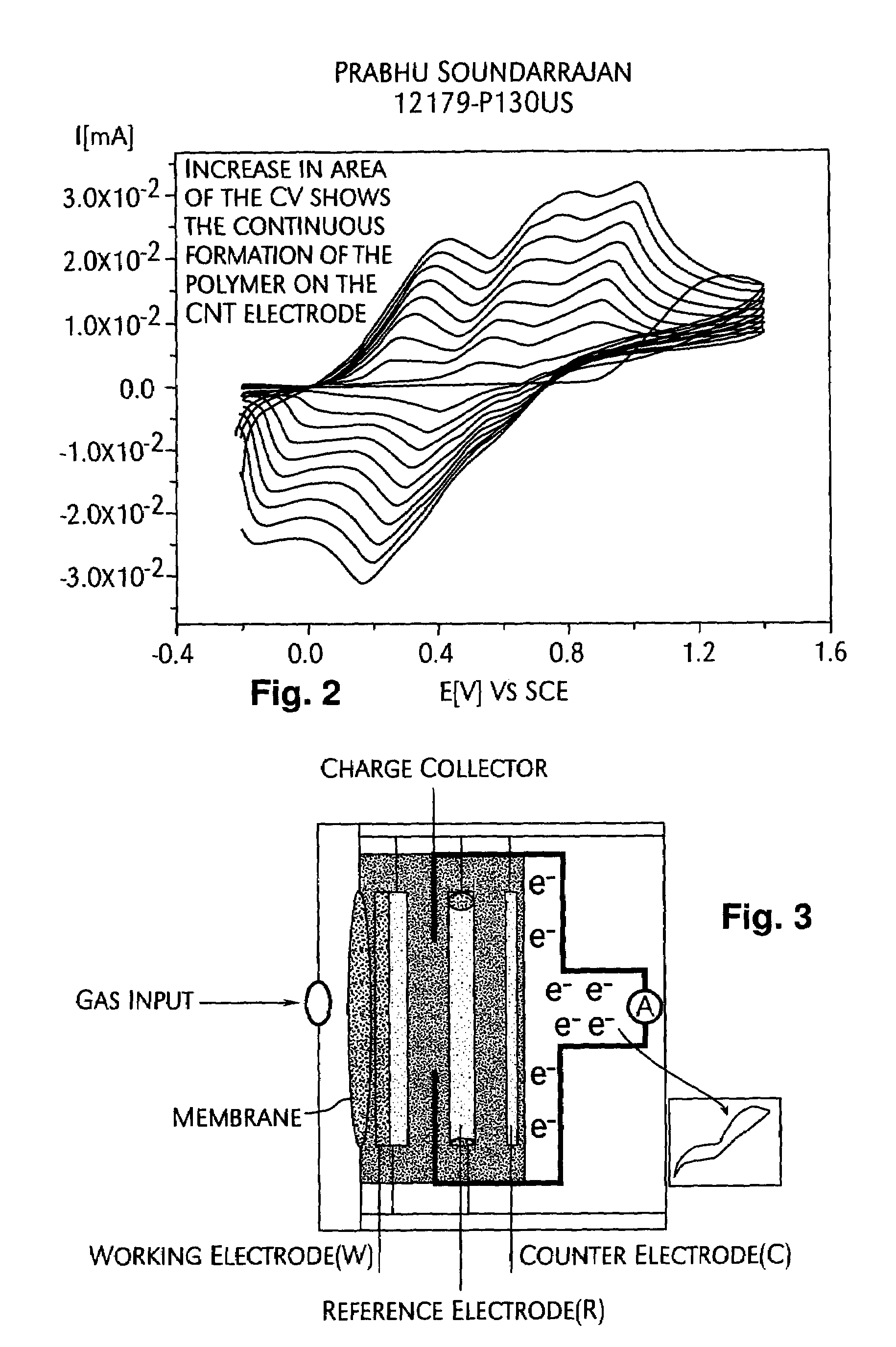
[0107]Electrochemical polymerization onto the carbon nanotube electrodes (applicable to all the electrodes discussed above) was carried out by the oxidation of aniline (0.1 M) in a solution containing 1 M H2SO4 in a pH 7.0 buffer solution. A potential window of −1.04 V to 0.96 V was employed for the electropolymerization with a scan rate of 50 mV / s for 10 cycles. Electropolymerization to form the polypyrrole was carried out by the oxidation of pyrrole (0.1 M) in a solution containing 0.1 M NaClO4 in a pH 7.0 buffer solution under the same electrochemical conditions. The electrodes were washed with water and dried in air.


PUM

PropertyMeasurementUnit
anodic potentialsaaaaaaaaaa
areaaaaaaaaaaa
lengthsaaaaaaaaaa

Abstract

The present invention is directed to systems and methods for detecting biological and chemical species in liquid and gaseous phase. The systems and methods utilize carbon nanotubes to enhance sensitivity and selectivity towards the reacting species by decreasing interference and detecting a wide range of concentrations.

Description

CROSS-REFERENCE TO RELATED APPLICATIONS[0001]The present application claims priority to U.S. Provisional Application Ser. No. 60 / 507,436 filed Sep. 30, 2003 and U.S. Provisional Application Ser. No. 60 / 598,293 filed Aug. 3, 2004.TECHNICAL FIELD[0002]The present invention relates in generally to systems and methods for chemical and biological detection, and more specifically to systems and methods of detecting chemical and biological analytes in various phases utilizing nanotubes.BACKGROUND INFORMATIONNanobiosensor[0003]Biosensors are devices, which incorporate a biological element (e.g., enzyme, antibody) to detect chemical, biological and organic species. Biosensors have potential applications including, but not limited to, extreme environments (Dong et al., Electroanalysis, 15, 157, 2003), detection of food and pathogenic bacteria (Ivnitski et al., Electroanalysis, 12, 317, 2000), glucose monitoring (Wang, Electroanalysis 13, 983, 2001) and the food industry.[0004]Conventional sen...

Claims


Application Information

Patent Timeline
Patent Type & Authority Patents(United States)
IPC IPC(8): G01N27/26H01L
CPCB82Y10/00Y10S977/92Y10S977/957G01N27/02H10K10/40
Inventor SOUNDARRAJAN, PRABHUNOVAK, JAMES P.
Owner APPLIED NANOTECH HLDG
Learn More