
Automatic gain control circuit and method thereof and demodulation apparatus using the same

a gain control circuit and gain control technology, applied in the direction of gain control, multiplex communication, orthogonal multiplex, etc., can solve the problems of system crash and deterioration of communication efficiency, and achieve accurate level acquisition, prevent error occurrence, and high speed

Inactive Publication Date: 2008-07-08
SONY CORP
View PDF18 Cites 14 Cited by
  • Summary
  • Abstract
  • Description
  • Claims
  • Application Information

AI Technical Summary

Benefits of technology

[0027]The present invention was made in consideration with such a circumstance and has as an object thereof to provide an automatic gain control circuit able to realize high speed, accurate level acquisition and in turn able to prevent occurrence of error and able to prevent crashing of the system and a method of same and a demodulation apparatus using the same.
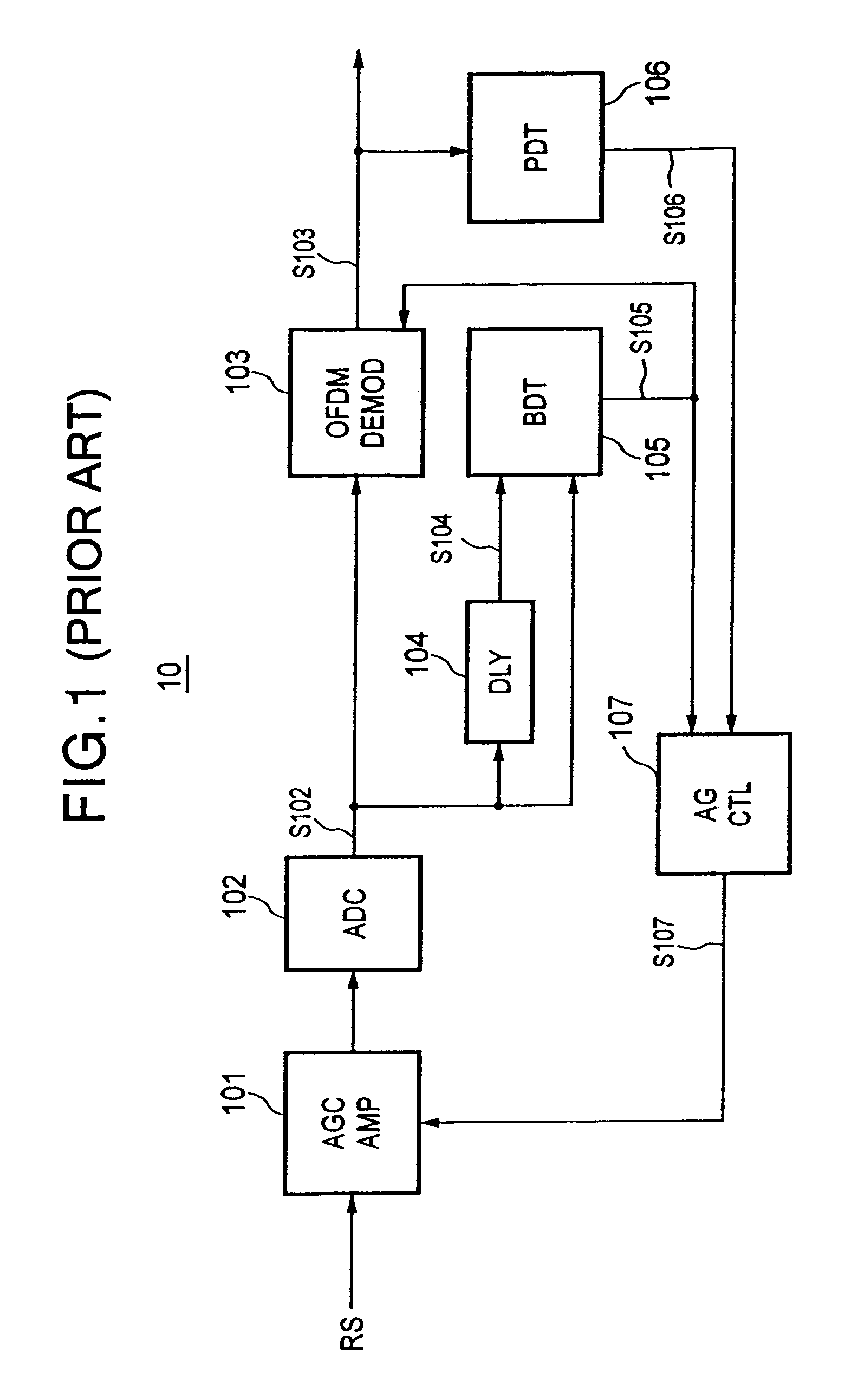
[0068]Note that, even if the preamble signal is distorted, since the burst detector uses an auto-correlation circuit, burst detection is possible without lowering the detection rate.

Problems solved by technology

As a result of this, there is the disadvantage that the optimum gain is gradually pulled into over several packets, error occurs in the header packet, and deterioration of communication efficiency due to resending of data or the like is induced.
Therefore, in an automatic gain control circuit having a long time constant, the optimum gain is not pulled into for the individual packets, but the mean gain of the optimum gains of all packets is pulled into and therefore there is the possibility that the system will end up crashing.

Method used


Image

  • Automatic gain control circuit and method thereof and demodulation apparatus using the same
  • Automatic gain control circuit and method thereof and demodulation apparatus using the same
  • Automatic gain control circuit and method thereof and demodulation apparatus using the same

Examples


Embodiment Construction

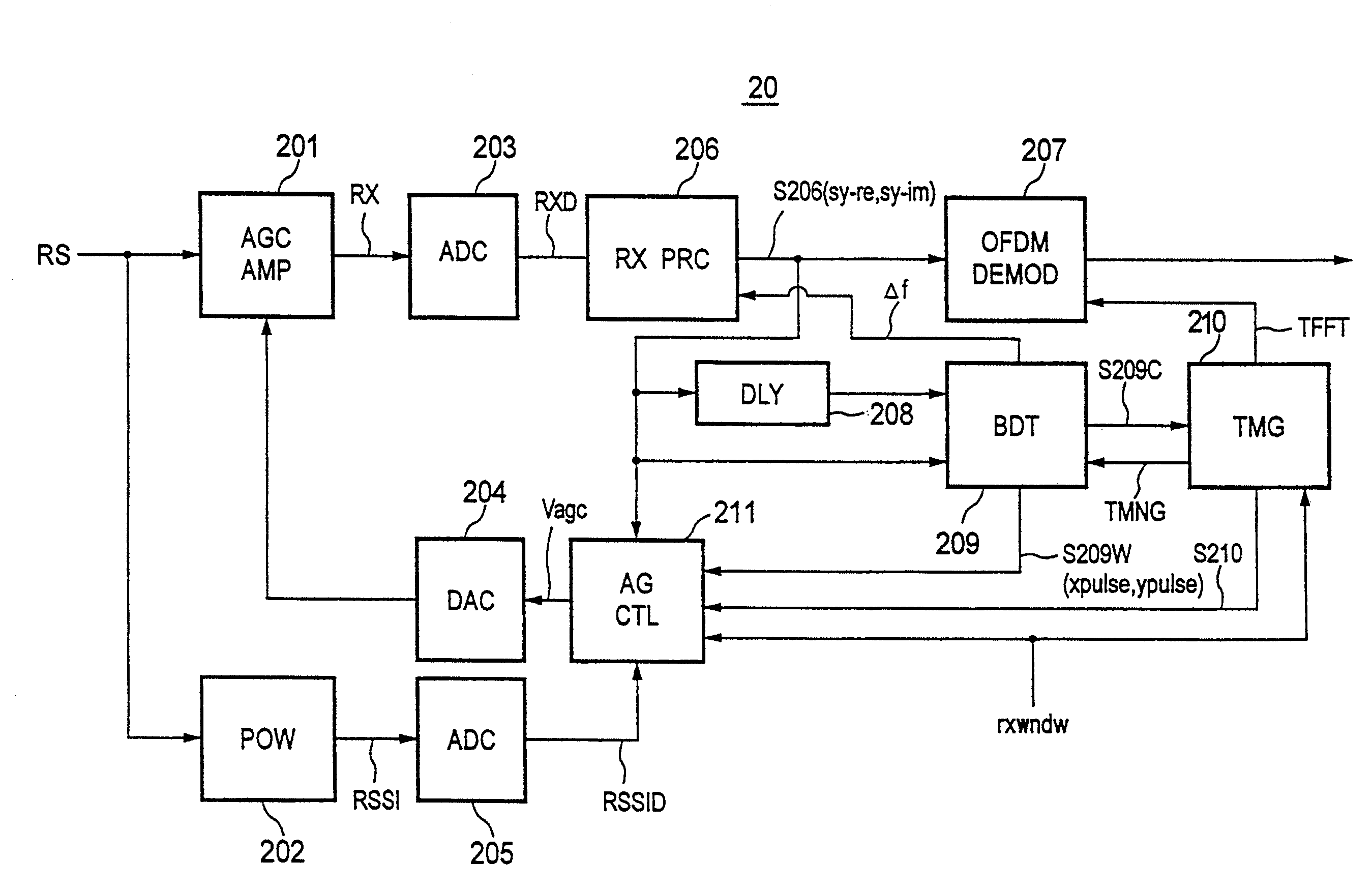
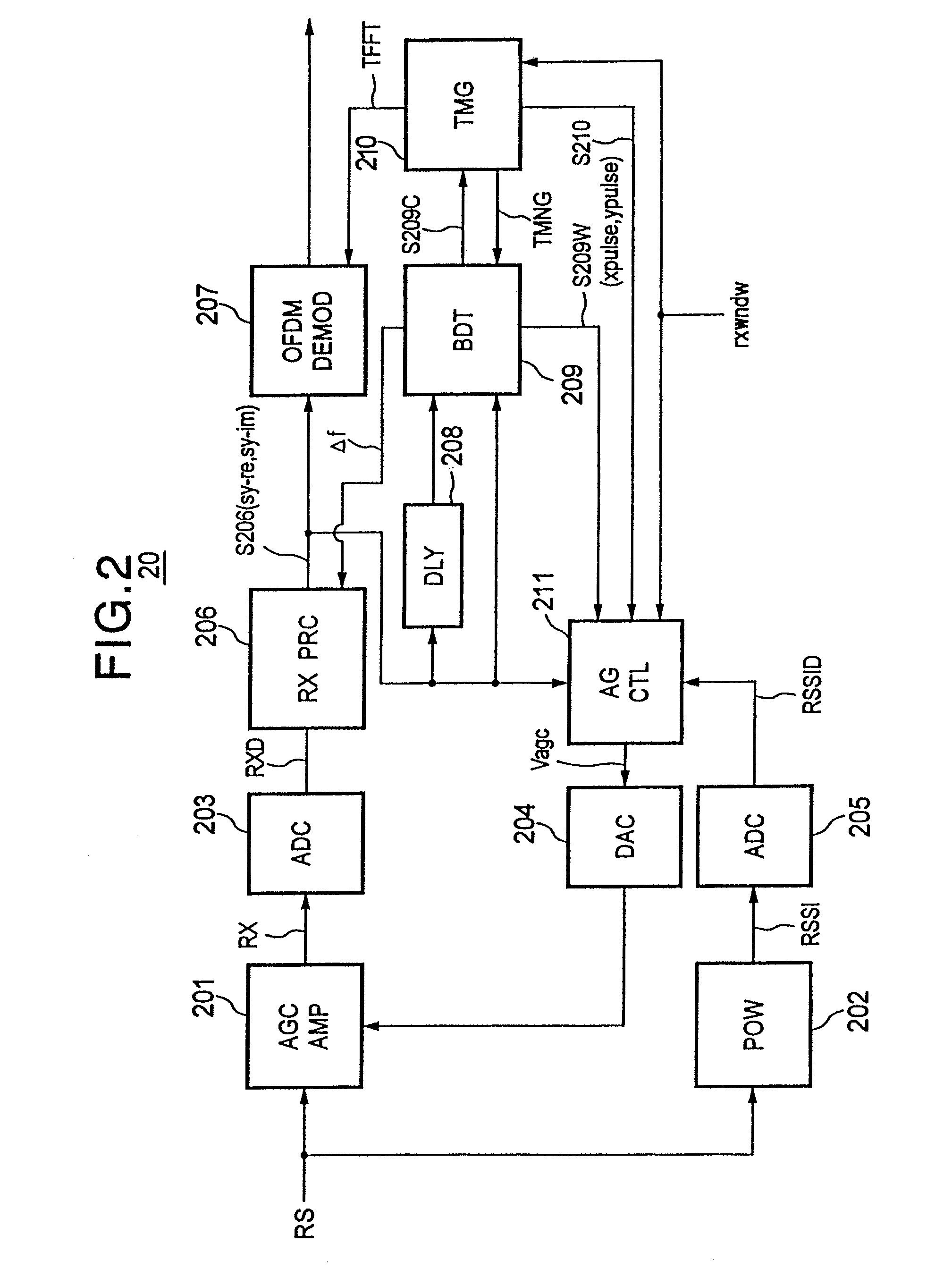
[0109]FIG. 2 is a block diagram of the configuration of an embodiment of a burst synchronization demodulation apparatus to which an automatic gain control circuit according to the present invention is applied.

[0110]The burst synchronization demodulation apparatus 20 has, as shown in FIG. 2, an automatic gain control amplifier (AGCAMP) 201, reception signal power monitor (POW) 202, A / D converter (ADC) 203, digital-to-analog analog (D / A) converter (DAC) 204, A / D converter (ADC) 205, reception signal processing unit (RXPRC) 206, OFDM demodulator (DEMOD) 207, delay unit (DLY) 208, burst detector (BDT) 209, timing controller (TMG) 210, and amplification gain controller (AGCTL) 211 as main components.

[0111]Below, the reason why the automatic gain control circuit according to the present invention is required for the burst synchronization communication system employed in the present embodiment, the transmission (reception) signal, and concrete configurations and functions of the components...


PUM


Abstract

An automatic gain control circuit able to perform high speed and correct level acquisition, able to prevent occurrence of error, and able to prevent a crash of the system. An amplification gain controller outputs a gain control signal to an automatic gain control amplifier to amplify the received signal with maximum value when receiving a burst detection trigger signal. A second gain control signal based on the detected reception signal power is calculated when receiving a first burst synchronization detection signal; and this second gain control signal is output to the automatic gain control amplifier. A received digital signal is amplified with the second gain and integrated to find the reception signal power, from which a third gain control signal is calculated and outputted to the automatic gain control amplifier to amplify the received signal with this third gain.

Description

TECHNICAL FIELD[0001]The present invention relates to an automatic gain control circuit applied to a receiver etc. of a wireless communication system and a method of the same and a demodulation apparatus using the same, more particularly relates to an automatic gain control circuit applied to for example a wireless communication system for receiving a radio signal which is modulated by an orthogonal frequency division multiplexing (OFDM) modulation method and includes a burst signal including a preamble signal at the header of this modulated packet signal, and a method of the same, and a demodulation apparatus using the same.BACKGROUND ART[0002]In a digital demodulation apparatus, there is a limit to the dynamic range of an analog-to-digital (A / D) converter for converting an analog signal to a digital signal.[0003]For this reason, a digital signal converted exceeding the dynamic range of the A / D converter will be output in a form including signal distortion.[0004]Further, in a syste...

Claims


Application Information

Patent Timeline
IPC IPC(8): H04L27/08H04B7/00H04L27/38H03G3/20H03G3/30H04B1/16H04J11/00H04L27/26
CPCH03G3/3052H04L27/2647H03G3/3078
Inventor KOMORI, KENJIWAKAMATSU, MASATAKASATO, HIDEAKIUSUI, TAKASHISAIJO, KAZUYUKITANABE, SHINICHIMOROHASHI, HIDEOFUJIMURA, KAZUHIRO
Owner SONY CORP
Learn More