
Fluid-filled vibration-damping device

a technology of vibration damping device and fluid filling, which is applied in the direction of shock absorbers, machine supports, mechanical devices, etc., can solve the problem of reducing the possibility of an impact upon bursting of bubbles, and achieve the effect of reducing costs and manufacturing with eas

Inactive Publication Date: 2008-07-08
SUMITOMO RIKO CO LTD
View PDF15 Cites 6 Cited by
  • Summary
  • Abstract
  • Description
  • Claims
  • Application Information

AI Technical Summary

Benefits of technology

[0010]It is therefore one object of this invention to provide a fluid-filled vibration damping device capable of minimizing noises caused by bubbles generated in a fluid chamber of the device.
[0013]In the fluid-filled vibration-damping device constructed according to this mode of the invention, the surface of the orifice-defining member is coated by the coating rubber layer at an area where the surface of the orifice-defining member defines the primary fluid chamber (hereinafter referred to as the “primary-fluid-chamber-defining area”), preferably at an area where the surface of the orifice-defining member defines the orifice passage (hereinafter referred to as the “orifice-passage-defining area”), as well. Accordingly, the area of the surface of the orifice-defining member exposed to the primary fluid chamber and the orifice passage remarkably reduced or minimized. Although a multiplicity of bubbles are likely to be generated and burst repeatedly within the fluid, especially in the primary fluid chamber subjected to a relatively large fluid pressure variation, when the fluid is forced to flow within the chamber due to the fluid pressure variation in the fluid chamber, the provision of the coating rubber layer makes it lower the possibility that an impact upon bursting of these bubbles is directly exerted on the surface of the orifice defining member. Therefore, a rate of occurrence of noises caused by the bursting of the bubbles is effectively reduced. Also, the elasticity of the coating rubber layer can absorb or minimize impact of bubble bursting applied on the coating rubber layer, thus minimizing an amount of noises undesirably transmitted to the outside of the mount. Thus, the fluid-filled vibration-damping device according to this mode of the invention is able to effectively avoid deterioration in silence and driving comfort of the vehicle.
[0014]That is, the fluid-filled vibration damping device according to this mode of the invention is capable of effectively preventing undesirably noises caused by the bubbles generated in the fluid within the fluid chamber, with the help of the coating rubber layer coating the surface of the orifice-defining member at the primary-fluid-chamber-defining area, preferably at the orifice-passage-defining area, as well.
[0015]According to this mode of the invention, the coating rubber layer can be easily bonded integrally with the orifice-defining member by vulcanizing a rubber material for forming the coating rubber layer in a mold cavity of a mold in which the orifice-defining member is preset. In order to prevent deformation of the orifice-defining member due to a pressure of the rubber material injected into the mold cavity, a plurality of pressing pins are formed on the surface of the mold cavity so that the orifice-defining member preset in the mold cavity is pressed or supported by the pressing pins. The mold coating rubber layer is not formed at respective locations where the plurality of pressing pins are held in contact with the flange portion of the orifice-defining member. In order to achieve an excellent noise reduction effect by means of the coating rubber layer, it is preferable to form the coating rubber layer on the surface of the orifice-defining member as wide as possible so that the orifice-defining member is hardly exposed to the primary fluid chamber and the orifice passage, except the above-described portion inevitably exposed to the primary fluid chamber and the orifice passage. The thickness of the coating rubber layer may be desirably determined. Preferably, the coating rubber layer may be formed also on yet another area of the orifice-defining member, which area is exposed to the auxiliary fluid chamber (hereinafter referred to as the “auxiliary-fluid-chamber defining area”, where appropriate).
[0017]According to this mode of the invention, the coating rubber layer and the movable rubber plate are formed on the surface of the orifice-defining member with no gap formed therebetween, surely preventing the surface of the orifice-defining member from being exposed to the primary fluid chamber, the orifice passage and / or the auxiliary fluid chamber. In addition, the coating rubber layer can be manufactured with ease and at a reduced expense.

Problems solved by technology

Although a multiplicity of bubbles are likely to be generated and burst repeatedly within the fluid, especially in the primary fluid chamber subjected to a relatively large fluid pressure variation, when the fluid is forced to flow within the chamber due to the fluid pressure variation in the fluid chamber, the provision of the coating rubber layer makes it lower the possibility that an impact upon bursting of these bubbles is directly exerted on the surface of the orifice defining member.

Method used


Image

  • Fluid-filled vibration-damping device
  • Fluid-filled vibration-damping device
  • Fluid-filled vibration-damping device

Examples


first embodiment

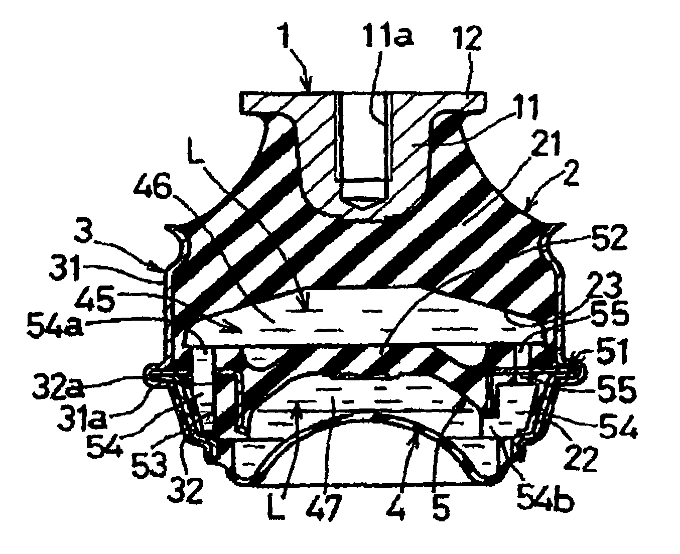
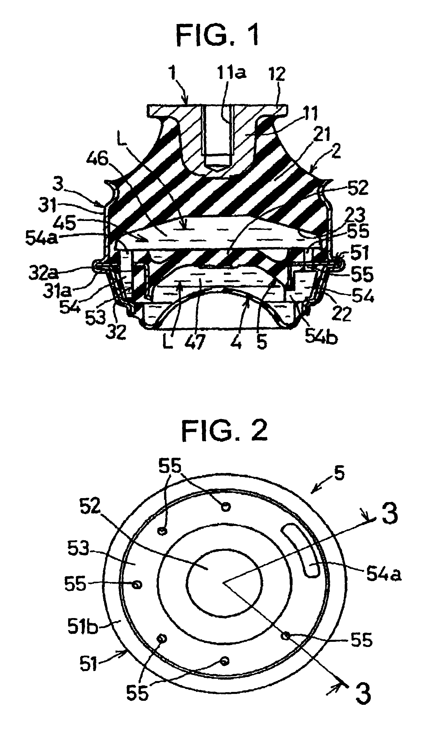
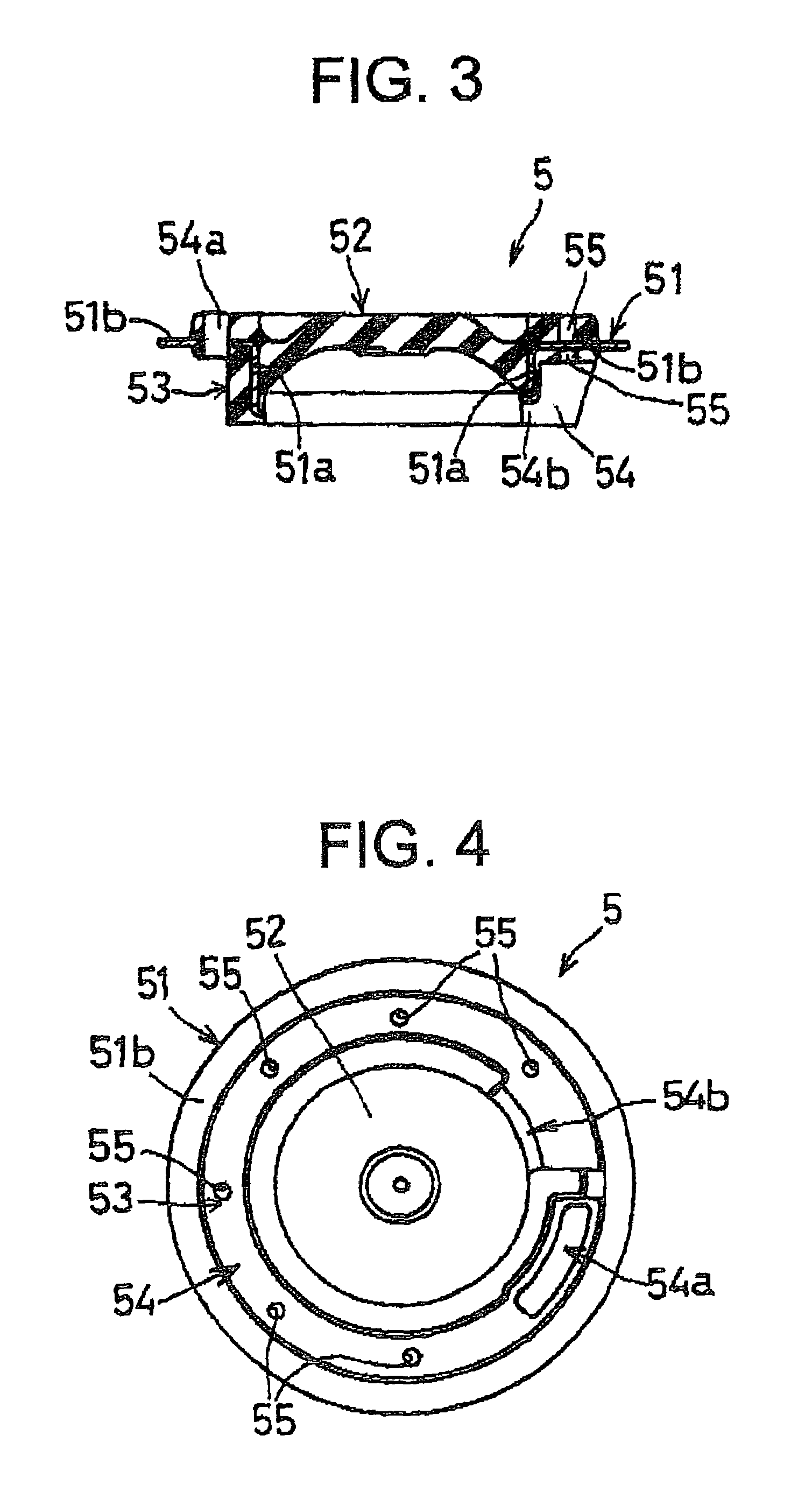
[0027]FIG. 1 is an elevational view in axial cross section of a fluid-filled vibration-damping device constructed according to the present invention. FIG. 2 is a top plane view of a partition member of the fluid-filled vibration-damping device. FIG. 3 is a cross sectional view taken along line 3-3 of FIG. 2. FIG. 4 is a bottom plane view of the partition member of the fluid-filled vibration-damping device.

[0028]As shown in FIG. 1, the fluid-filled vibration-damping device includes: a first mounting member 1; an elastic body 2 bonded at one end to the first mounting member and having a recess 23 at the other end; a cylindrical second mounting member 3 bonded to the other end of the elastic body 2; a diaphragm 4 whose peripheral portion is supported by an inner circumferential surface of the second mounting member 3 so that the diaphragm 4 cooperates with the elastic body 2 to define therebetween a fluid chamber 45 filled with a fluid “L”; and a partition member 5 whose peripheral por...

second embodiment

[0049]The said second embodiment as described above makes it easy to manufacture the coating rubber layer 63 while surely preventing the deformation of the orifice-defining member 61 relative to the mold when vulcanizing a rubber material for forming the coating rubber layer 63.


PUM


Abstract

A fluid-filled vibration-damping device includes an elastic body elastically connects a first mounting member and a cylindrical second mounting member bonded to opposite side thereof; a diaphragm supported by the second mounting member so that the diaphragm cooperates with the elastic body to define therebetween a fluid chamber; and a partition member supported by the second mounting member so that the partition member divides the fluid chamber into a primary fluid chamber and an auxiliary fluid chamber which are held in communication through an orifice passage defined by an orifice-defining member having a movable rubber plate disposed in its central hole. The surface of the orifice-defining member is coated at a primary-fluid-chamber-defining area by a coating rubber layer, thereby minimizing noises caused by bubbles in the fluid chamber.

Description

INCORPORATED BY REFERENCE[0001]The disclosure of Japanese Patent Application No. 2002-121256 filed on Apr. 23, 2003 including the specification, drawings and abstract is incorporated herein by reference in its entirety.BACKGROUND OF THE INVENTION[0002]1. Field of the Invention[0003]The present invention relates to a fluid-filled vibration damping device suitably applicable to engine mounts, body mounts or other mounts for use in automotive vehicles, for example.[0004]2. Description of the Related Art[0005]In automotive vehicles each having an engine as a vibrational source, an engine mount has been used for supporting the engine on a body frame of the vehicle in a vibration isolating fashion. FIG. 8 shows an example of such an engine mount in the form of a fluid-filled vibration-damping device.[0006]The known fluid-filled vibration damping device includes: a first mounting member 101 of shaft configuration; a rubber elastic body 102 bonded at one end to the first mounting member and...

Claims


Application Information

Patent Timeline
IPC IPC(8): F16F5/00F16F13/10
CPCF16F13/105
Inventor HIBI, SATORUINOUE, CHIYAKI
Owner SUMITOMO RIKO CO LTD
Learn More