Reduction of heat loss in micro-fluid ejection devices

a technology of microfluid ejection and heat loss reduction, which is applied in the direction of printing, etc., can solve the problems of unsatisfactory and potentially damaging overheating of increased heat generated in the microfluid ejection head, and damage to delicate semiconductor structures in the substrate. , to achieve the effect of reducing energy consumption, minimizing heat loss, and reducing the energy consumption of the fluid ejector actuator

Inactive Publication Date: 2008-06-24
FUNAI ELECTRIC CO LTD
View PDF15 Cites 8 Cited by
  • Summary
  • Abstract
  • Description
  • Claims
  • Application Information

AI Technical Summary

Benefits of technology

[0005]For example, with reference to FIG. 1, conventional micro-fluid ejection head 10 include a semiconductor substrate 12, e.g., a silicon substrate, having an oxide barrier layer 14 applied thereto to serve as a thermal barrier between the silicon substrate and a resistive layer 16 that provides the fluid ejector actuators 17. One or more protective layers 18 are provided on the resistive layer 16 to protect the resistive layer from chemical and mechanical damage. The oxide barrier layer 14 is typically a relatively dense and substantially continuous film of a thermal oxide with, optionally, a layer of borophososilicate glass on one side thereof. Conventional oxide barrier layers 14 function to prevent the energy from the ejector actuators 17 from migrating into the silicon substrate 12. However, the specific heat of the barrier layer 14 typically results in a significant absorption or collection by the barrier layer 14 of heat from the ejector actuators, which results in heat losses that reduce the thermal efficiency of the micro-fluid ejection head 10.
[0006]Therefore, a need exists for a way to reduce heat losses to adjacent layers of a micro-fluid ejection head to provide semiconductor devices, such as micro-fluid ejection heads, having improved thermal and electrical efficiency.
[0009]Yet another embodiment of the disclosure provides a method for reducing energy consumption for a micro-fluid ejection head. The method includes depositing a thermal insulating layer having a thermal conductivity of less than about 1 W / m-K on a semiconductor support substrate. A resistive layer is deposited on the semiconductor support substrate to provide a fluid ejector actuator. The thermal insulating layer is disposed between the resistive layer and the support substrate.
[0010]According to exemplary embodiments provided herein, the porous, substantially impermeable material providing the insulating layer serves to reduce the flow of heat from the ejector actuators toward the silicon layer, thus minimizing heat losses during activation of the ejector actuators during fluid ejection operations.
[0011]The above described embodiment improves upon the prior art in a number of respects. The structure of the present disclosure may significantly lower the energy consumption of the fluid ejector actuator by reducing heat dissipation to the area surrounding the ejector actuator and thereby minimize problems associated with over heating of the substrate. The disclosure lends itself to a variety of applications in the field of micro-fluid ejection devices, and particularly in regards to energy efficient inkjet printheads.

Problems solved by technology

Excess energy may result in an undesirable and potentially damaging overheating of the micro-fluid ejection head.
Unfortunately, as the number of ejection pulses in any given amount of time increases, the heat generated in the micro-fluid ejection head also increases.
If the ejection head becomes too hot, the delicate semiconductor structures in the substrate may be damaged.
However, the specific heat of the barrier layer 14 typically results in a significant absorption or collection by the barrier layer 14 of heat from the ejector actuators, which results in heat losses that reduce the thermal efficiency of the micro-fluid ejection head 10.

Method used


Image

  • Reduction of heat loss in micro-fluid ejection devices
  • Reduction of heat loss in micro-fluid ejection devices
  • Reduction of heat loss in micro-fluid ejection devices

Examples


Embodiment Construction

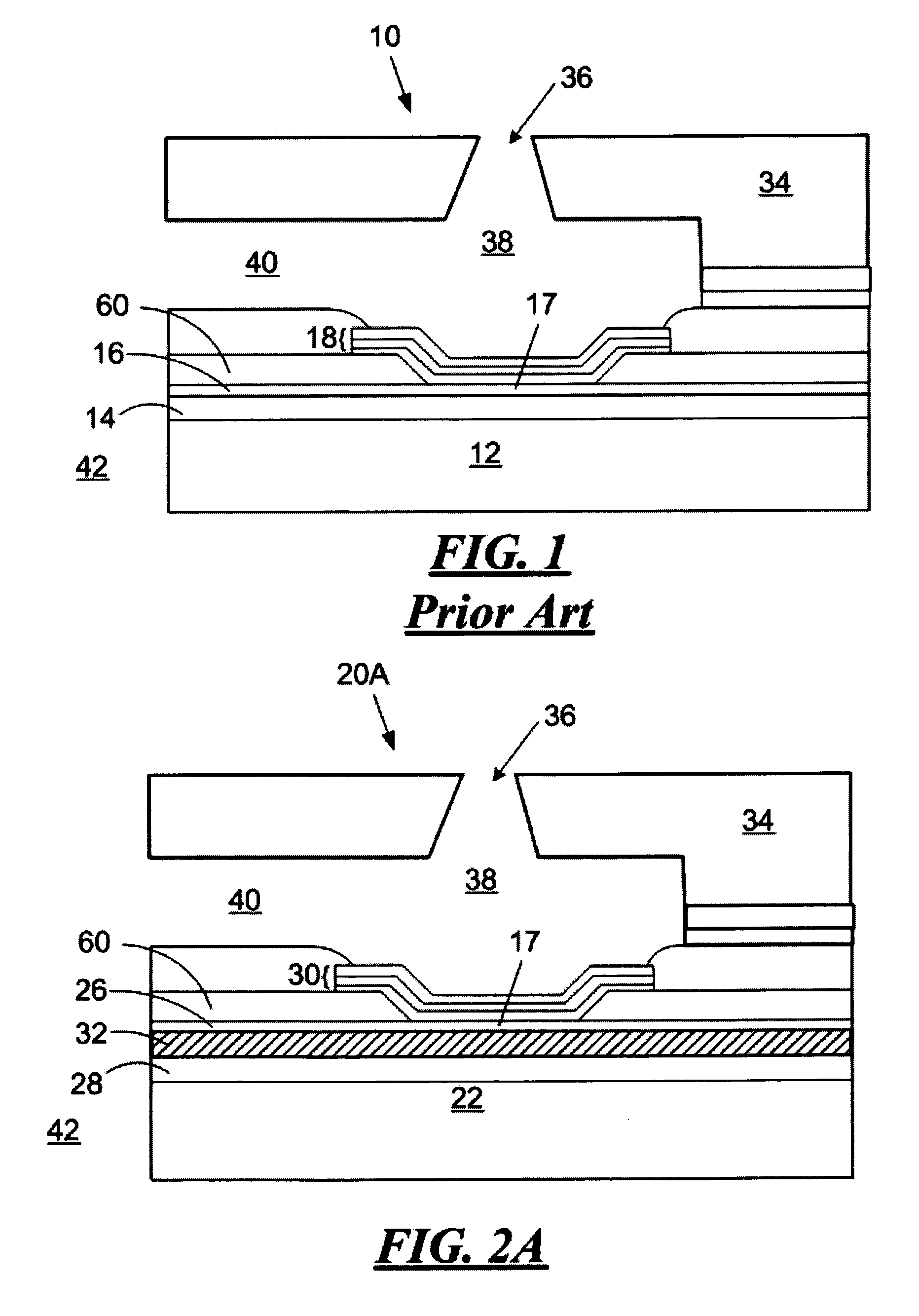
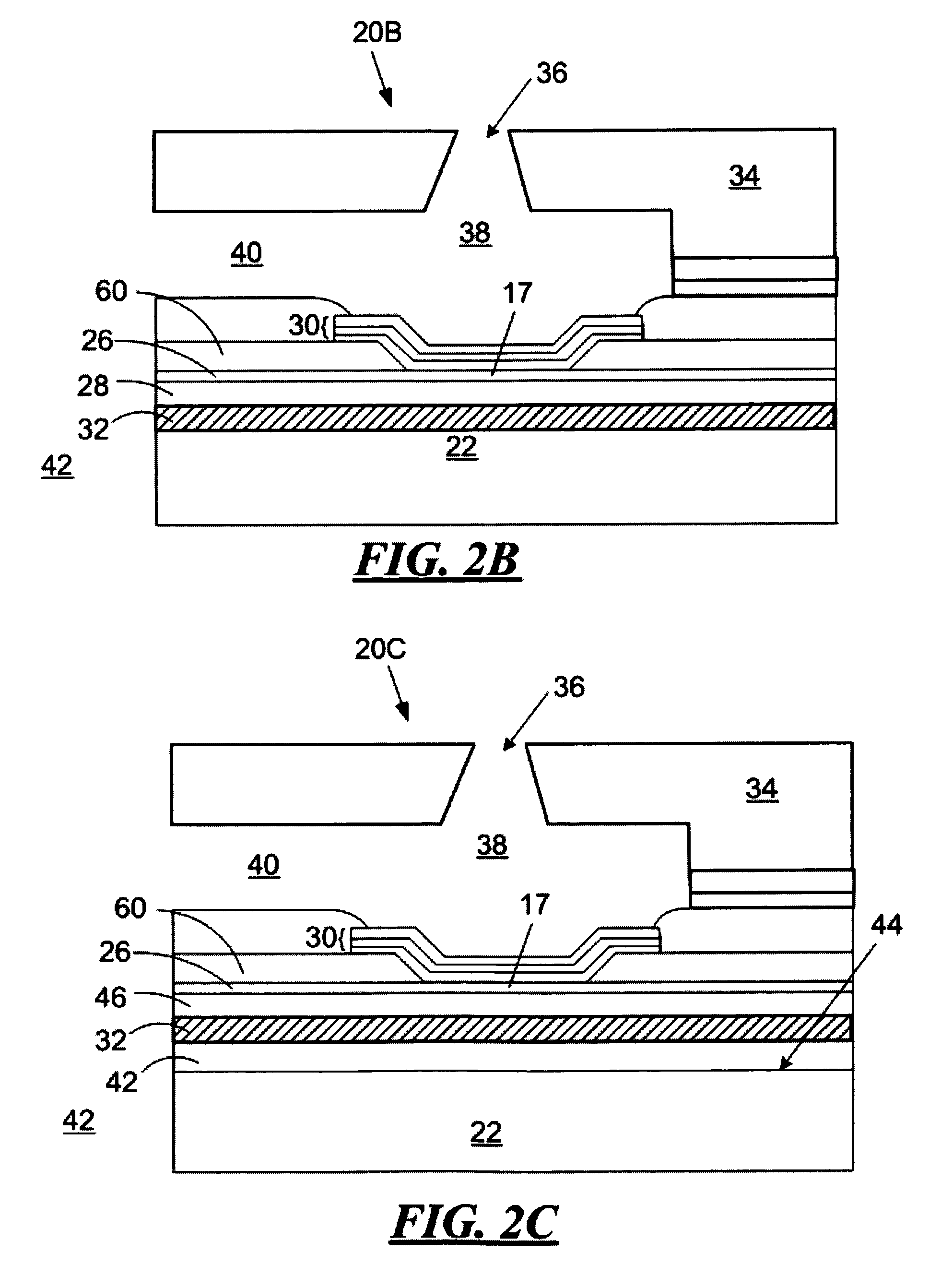
[0019]Referring now to FIGS. 2A-2C, micro-fluid ejection heads 20A-20C according to exemplary embodiments of the present disclosure are illustrated. Each of the ejection heads 20A-20C may include an ejector actuator 17, such as resistance heaters, made using conventional semi-conductor manufacturing techniques such as chemical vapor deposition (CVD), sputtering, spinning, physical vapor deposition (PVD), etching and the like. The ejection actuators may also be provided by other micro-fluid ejection devices, such as piezoelectric actuators. The ejection heads 20A-20C of the exemplary embodiments advantageously incorporate a low thermal diffusivity film between the ejector actuator 17 and the underlying semiconductor substrate 22 to advantageously inhibit heat loss from activation of the fluid ejector actuator 17.

[0020]Referring now to FIG. 2A, there is shown a fluid ejection head 20A for use in a micro-fluid ejection device. The ejection head 20A includes a semiconductor substrate 22...


PUM


Abstract

The present disclosure is directed to a micro-fluid ejection head for a micro-fluid ejection device. The head includes a semiconductor substrate, a fluid ejection actuator supported by the semiconductor substrate, a nozzle member containing nozzle holes attached to the substrate for expelling droplets of fluid from one or more nozzle holes in the nozzle member upon activation of the ejection actuator. The substrate further includes a thermal insulating barrier layer between the semiconductor substrate and the fluid ejection actuator. The thermal insulating barrier layer includes a porous, substantially impermeable material having a thermal conductivity of less than about 1 W / m-K.

Description

FIELD OF THE DISCLOSURE[0001]The present disclosure is generally directed to an improved micro-fluid ejection device. More particularly, the disclosure is directed toward the use of certain insulating materials to improve the energy efficiency of a fluid ejection actuator by reducing heat losses from the ejection actuator to an underlying semiconductor substrate.BACKGROUND AND SUMMARY[0002]A micro-fluid ejector device, such as a thermal ink jet printer, forms an image on a printing surface by ejecting small droplets of ink from an array of nozzles on an ink jet printhead as the printhead traverses the print medium. The fluid droplets are expelled from a micro-fluid ejection head when a pulse of electrical current flows through the fluid ejector actuator on the ejection head. When the fluid ejection actuator is a resistive fluid ejector actuator, vaporization of a small portion of the fluid creates a rapid pressure increase that expels a drop of fluid from a nozzle positioned over th...

Claims


Application Information

Patent Timeline
Patent Type & Authority Patents(United States)
IPC IPC(8): B41J2/05
CPCB41J2/14129
Inventor BELL, BYRON V.CORNELL, ROBERT W.GUAN, YIMINJOYNER, II, BURTON L.
Owner FUNAI ELECTRIC CO LTD
Why Eureka
Try Eureka