
Rate limiting data traffic in a network

Active Publication Date: 2008-06-17
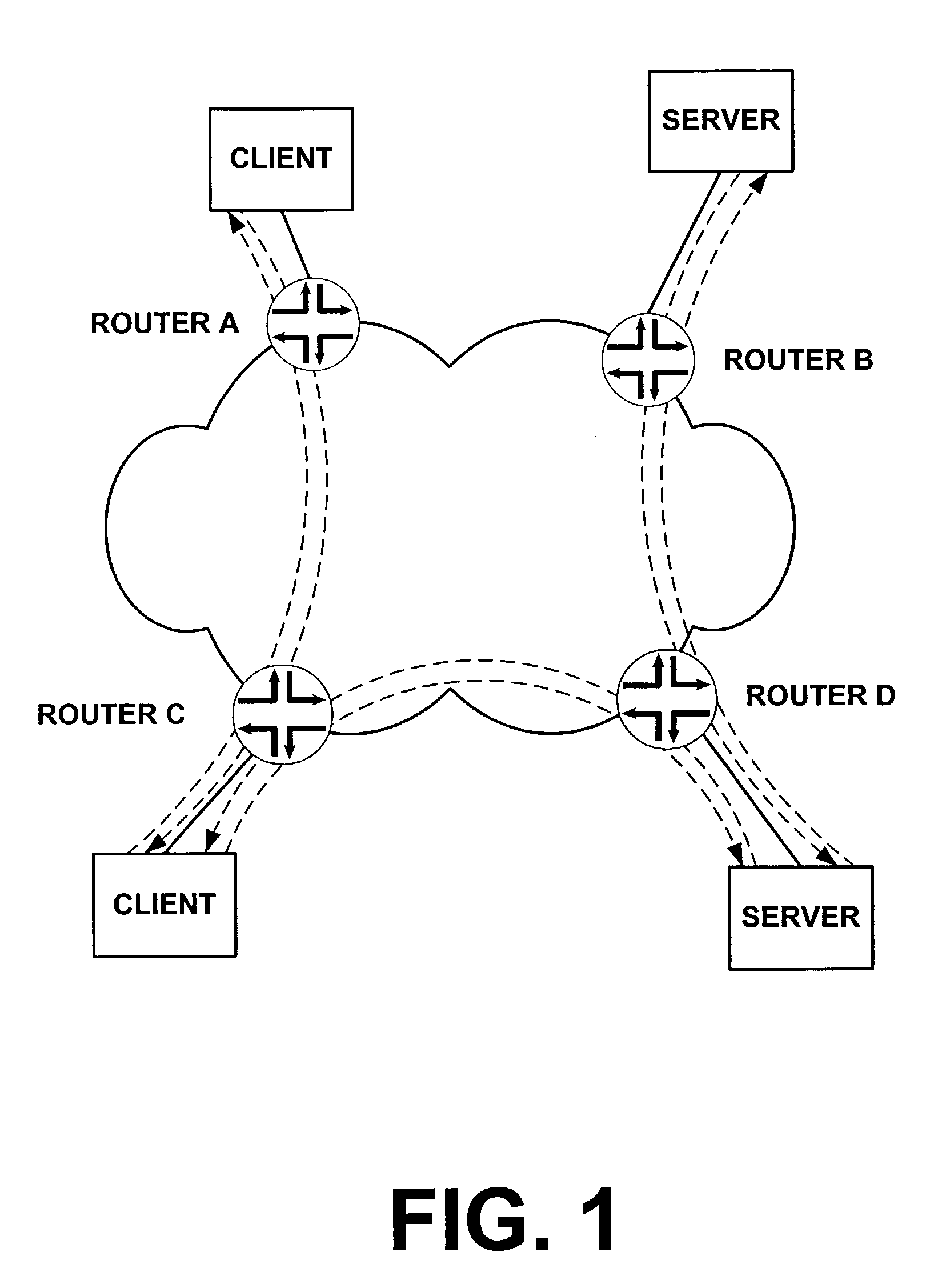
JUMIPER NETWORKS INC
View PDF29 Cites 219 Cited by
  • Summary
  • Abstract
  • Description
  • Claims
  • Application Information

AI Technical Summary

Benefits of technology

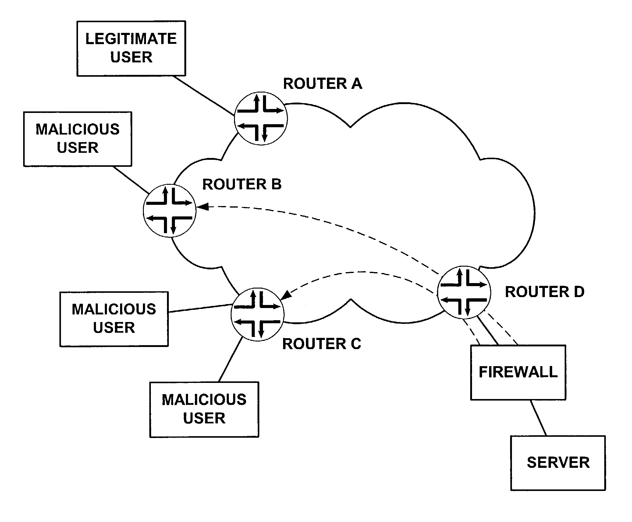
[0026]In yet another implementation consistent with the principles of the invention, a system for detecting and responding to an attack is provided. The system includes a first device configured to receive and forward data in a network and count an amount of received data having particular characteristics. The first device is also configured to transmit first control information via the network, where the first control information includes information representing the counted amount. The system also includes at least one second device configured to receive the first control information, generate second control information based on the first control information and transmit the second control information. The system further includes at least one third device configured to receive the second control information and limit a rate at which data is forwarded by the third device based on the second control information.

Problems solved by technology

Sometimes, however, networks restrict access in certain ways.
For example, a corporate network may limit network access to only employees of that corporation and customers.
Although certain areas of a corporate network may be accessed by employees and customers, other certain areas may be limited to access by employees only.
Every server, however, has a limit as to the rate it can respond to requests for services.
If requests arrive too rapidly, service may be adversely affected if the servers cannot keep up with the rate of requests.
Similarly, a given router, and a given communications link, also has a capacity limit.
Networks are under almost constant attacks by malicious users who wish to disrupt the network.
Ultimately, the server is so overloaded that adequate service to legitimate clients is denied.
The computer systems are usually innocent and are being used by someone to unwittingly carry out the attack.
This results in a very large traffic load on the server and sometimes also on communications links used to access the server.
This results in some combination of failure of the server, severe congestion on communications resources, such as links or routers in the network, or seriously disrupted service to legitimate users.
In a DOS attack, for example, any one request might be valid when considered alone, but when multiple requests are considered together a malicious attack might be identified.
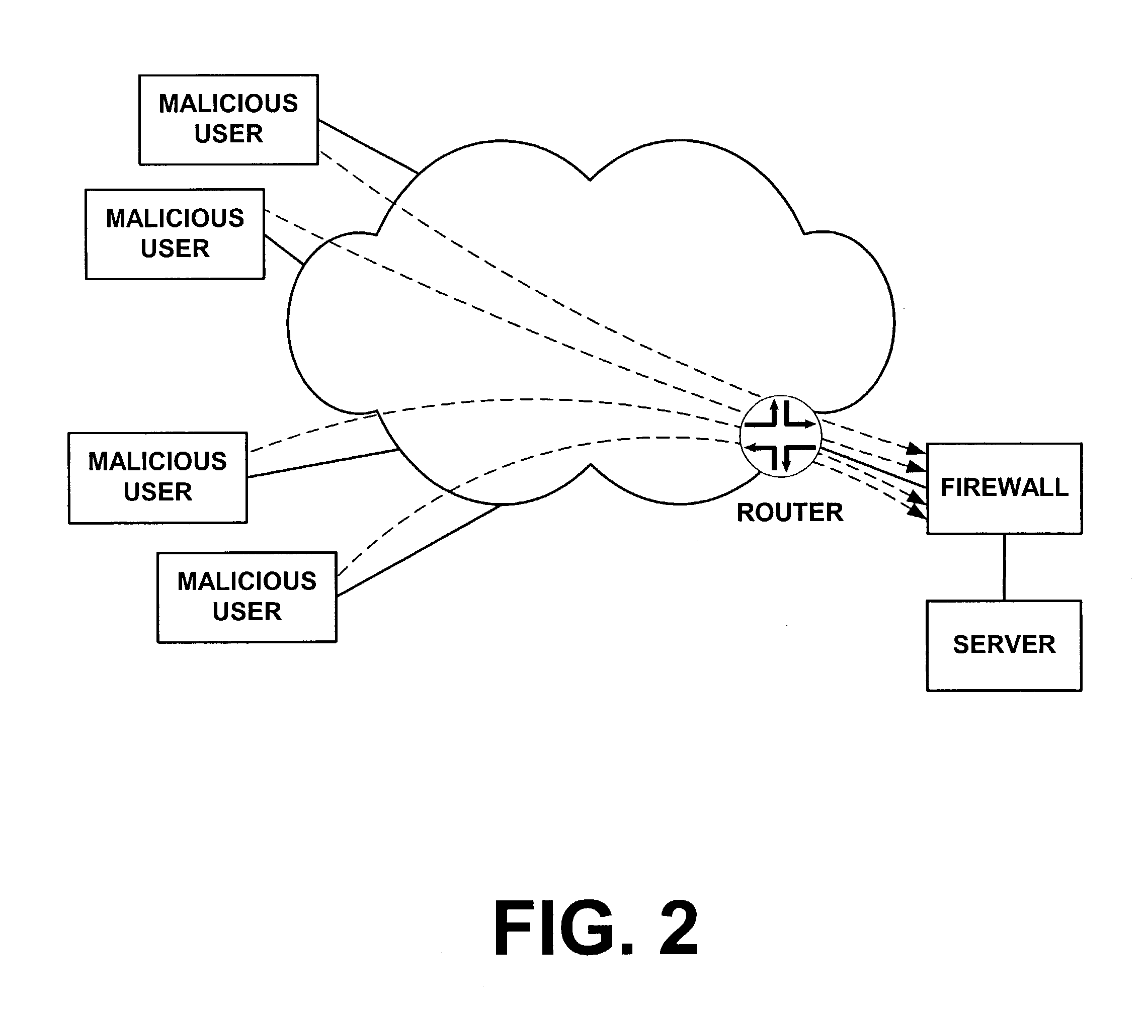
The malicious packets arriving at a single location creates other problems in addition to overloading the server.
The link from the router to the firewall may itself become so congested that service is denied.
Thus, even if malicious packets are successfully discarded at the firewall, the loss of bandwidth on the link between the router and the server or firewall still represents a significant denial of service.
A sufficiently large attack may also congest other links in the communications network.
Another problem may arise because operation of the firewall consumes considerable resources.
Thus, even after a firewall detects an attack, it still needs to spend some amount of CPU resources to discard each malicious packet.
This problem is more of an issue when the firewall is running on the server, and is not as drastic in the physically separate firewall implementation illustrated in FIG. 2 because in the physically separate implementation the server itself does not consume its resources discarding packets.
The firewall in FIG. 2, however, represents additional cost to the network.
In addition, the network resources, including but not limited to the link from the local router to the firewall or server, need to carry the additional traffic, which therefore also represents wasted resources.

Method used


Image

  • Rate limiting data traffic in a network
  • Rate limiting data traffic in a network
  • Rate limiting data traffic in a network

Examples


management embodiment

Central Management Embodiment

[0130]FIG. 12 illustrates a distributed filtering system using a central management system consistent with the principles of the invention. The distributed filtering system of FIG. 12 includes a physically separate firewall as well as a server configured with a firewall 1202. Each firewall participates in detecting an attack. In response to detecting an attack, or some sort of indication of an attack, each firewall creates attack information defining what has been detected regarding the attack, and sends the attack information to router D and central management system 1210. The attack information may come from one or both of the firewalls.

[0131]Central management system 1210 receives the attack information and uses the information to assist in coordinating a response to the attack. For example, central management system 1210 may forward the attack information directly to routers B and C, the routers connected to malicious users. Central management system...


PUM


Abstract

A network device coordinates with other devices in a network to create a distributed filtering system. The device detects an attack in the network, such as a distributed denial of service attack, and forwards attack information to the other devices. The devices may categorize data into one or more groups and rate limit the amount of data being forwarded based on rate limits for the particular categories. The rate limits may also be updated based on the network conditions. The rate limits may further be used to guarantee bandwidth for certain categories of data.

Description

RELATED APPLICATIONS[0001]This application is a continuation-in-part of U.S. patent application Ser. No. 10 / 080,865 entitled Distributed Filtering for Networks filed Feb. 21, 2002, the disclosure of which is incorporated herein by reference, which claims priority under 35 U.S.C. § 119 based on U.S. Provisional Patent Application No. 60 / 328,489, filed Oct. 9, 2001. This application claims priority of U.S. Provisional Application No. 60 / 328,489, the disclosure of which is also incorporated herein by reference.BACKGROUND OF THE INVENTION[0002]The present invention relates generally to data processing systems and, more particularly, to systems and methods for filtering network traffic based on attacks.[0003]The Internet consists of multiple interconnected networks that transfer data between a large number of devices, such as servers and clients. Routers are used to transfer the data in packets over communication links that connect the routers, clients, and servers.[0004]Protocols specif...

Claims


Application Information

Patent Timeline
IPC IPC(8): G06F11/00
CPCH04L47/10H04L63/0218H04L63/1458H04L63/0263H04L63/1425H04L63/1416H04L63/1441
Inventor CALLON, ROSS W.KASTENHOLZ, FRANK
Owner JUMIPER NETWORKS INC
Learn More