
Lab animal tracker and deterministic shocker

a deterministic shocker and animal tracker technology, applied in the field of deterministic shockers, can solve the problems of electric burn to the animal, lack of knowledge of the location of the test animal, and different ways of animal shock, so as to minimize the risk of injury to the animal, simple design and construction, and high consistency

Inactive Publication Date: 2008-06-03
FLORIDA STATE UNIV RES FOUND INC
View PDF9 Cites 16 Cited by
  • Summary
  • Abstract
  • Description
  • Claims
  • Application Information

AI Technical Summary

Benefits of technology

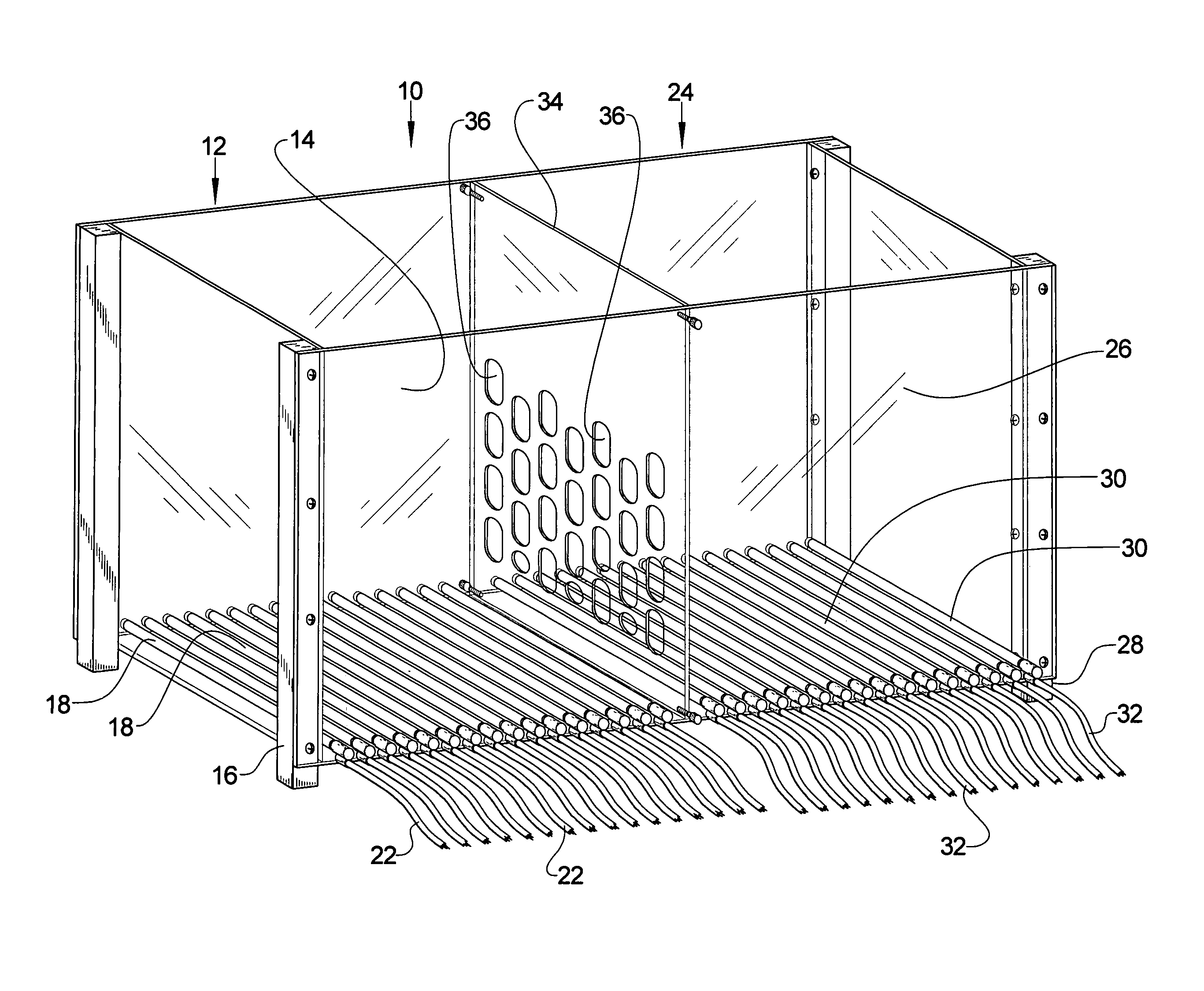
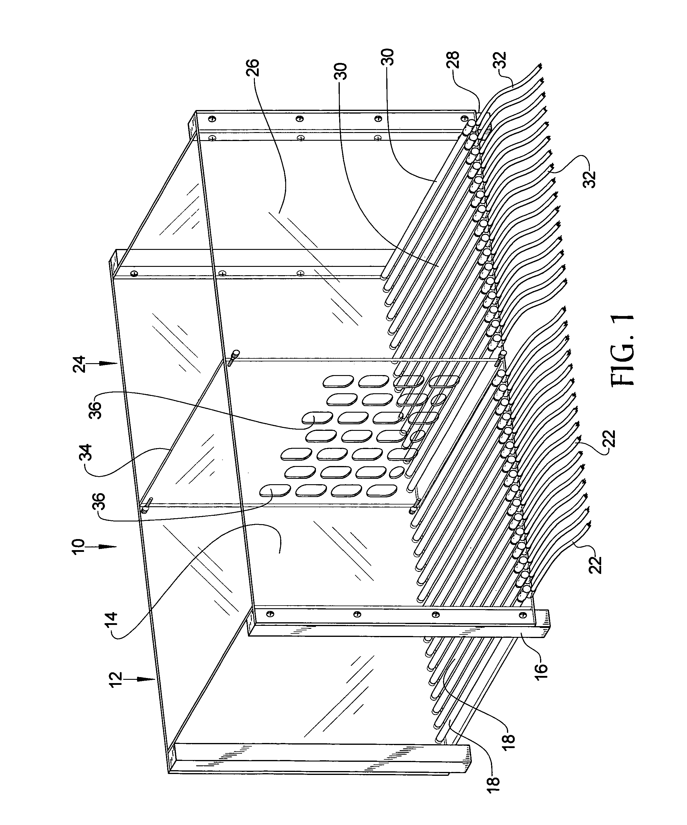
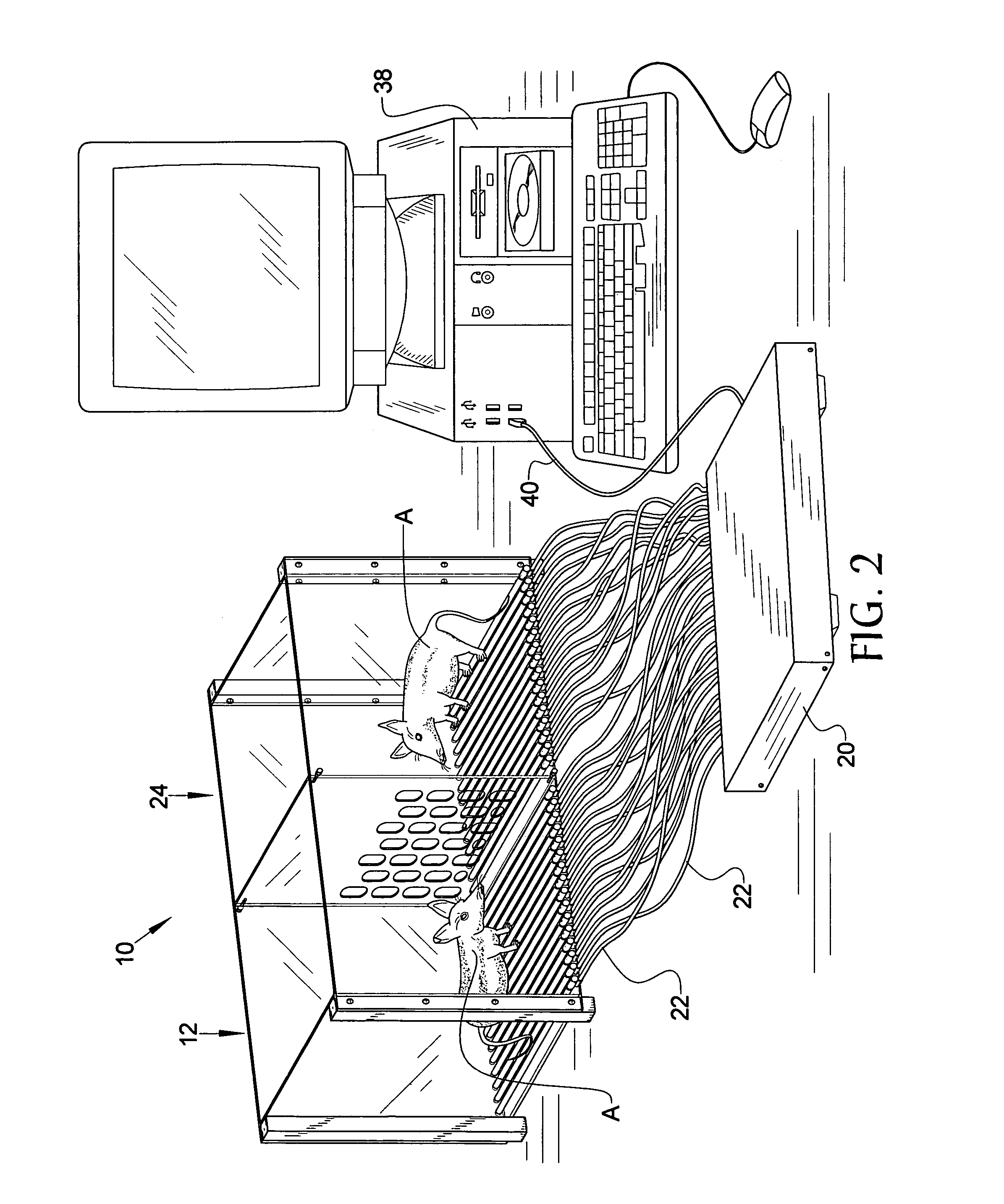
[0008]The lab animal tracker and deterministic shocker of the present invention addresses the aforementioned needs in the art by providing a device that determines upon which electrode an animal's paws are located and delivers an electric shock only to that electrode. This gives a researcher high consistency between experiment runs and minimizes the risk of injury to the animal from an improperly delivered electric current. The lab animal tracker and deterministic shocker is capable of recording the movements of an animal throughout the experiment so that a researcher can study the movements of the animal after conclusion of the experiment. The lab animal tracker and deterministic shocker has the capacity to hold a second animal separated from the first animal by a transparent enclosure and measure and record the movements of the second animal without shocking the second animal so that a researcher can also record and study the movements of the second animal in response to the second animal witnessing the shocking of the first animal during an experiment. The lab animal tracker and deterministic shocker is of relatively simple design and construction and is easy to setup, use, and maintain.

Problems solved by technology

The problem with the present systems is that they lack knowledge of the location of the test animal on the grid floor.
However, the sequential placement of the shocks is ordered in some fashion thereby leading to the animal being shocked in differing ways from experiment to experiment.
Another problem with such systems is the potential to cause an electric burn to the animal due to high intensity localized power dissipation.
As the shocker applies power to this electrode, a burn can result due to the high voltage and corresponding high power density at this point of contact.
Just one watt of power can result in burning a lab animal.

Method used


Image

  • Lab animal tracker and deterministic shocker
  • Lab animal tracker and deterministic shocker
  • Lab animal tracker and deterministic shocker

Examples


Embodiment Construction

[0013]Referring now to the drawings, it is seen that the lab animal tracker and deterministic shocker of the present invention, generally denoted by reference numeral 10, is comprised of an enclosure 12 that has at least a front wall 14 that is transparent for easy viewing of the animal A located therein. Located proximate the base 16 of the enclosure 12 is a grid floor that is comprised of a series of generally parallel electrically conductive rods 18, each rod 18 serving as an electrode. The number of rods 18 can vary and is determined by the size of the enclosure 12, the size of the animal A within the enclosure, etc. A controller 20 is provided and each rod 18 is electrically connected with the controller 20 by an appropriate wire 22. The wires 22 may be individually strung as illustrated, or may be bundled together and have an appropriate interface (not illustrated) that connects with an appropriate corresponding interface (also not illustrated) on the controller 20. As seen, a...


PUM


Abstract

A deterministic shocker holds a test animal within an enclosure on a grid floor of electrodes such that a controller places a small current across each electrode and measures the electrical resistance of each electrode. The electrode with the lowest resistance strongly correlates to the location of a paw of the animal so that the controller delivers a small electric shock to only that electrode. Animal movement can be tracked and recorded during an experimental run. A second enclosure may be located adjacent the first enclosure separated by a transparent partition wherein the second enclosure also has a grid floor comprised of a plurality of electrodes, The controller also places a current across each of these electrodes and measures the electrical resistance thereof so that this animal's movement can also be tracked during the experiment to measure this second animal's response in witnessing the shocking of the first animal.

Description

[0001]This application claims the benefit of provisional patent application No. 60 / 734,343 filed on Nov. 7, 2005, which provisional application is incorporated herein by reference.BACKGROUND OF THE INVENTION[0002]1. Field of the Invention[0003]The present invention relates to a device that tracks the movement of an animal within a research cage and delivers a well controlled and measured shock to the animal's feet. The device also allows the tracking of two animals that can see each other with one of the animals receiving the shocks.[0004]2. Background of the Prior Art[0005]It is often desirable to track the movement of an animal within a research cage while delivering a pain stimulus in order to measure the animal's response to the pain. For example, it may be desirable to track the movements of a mouse while receiving pain stimulus both before and after giving the mouse a newly developed pain medication in order to determine the efficacy of the drug. Of the various types of pain s...

Claims


Application Information

Patent Timeline
IPC IPC(8): G01M7/00A01K37/00
CPCA01K1/031
Inventor HENDERSON, ROSS P.BOLANOS, CARLOS A.
Owner FLORIDA STATE UNIV RES FOUND INC
Learn More