
Crystal oscillator device, oscillation method and heater

a crystal oscillator and oscillator technology, applied in the direction of oscillator generators, piezoelectric/electrostrictive/magnetostrictive devices, piezoelectric/electrostriction/magnetostriction machines, etc., can solve the problems of low thermal efficiency, difficult to guarantee the stable generation of the signals of two oscillation modes without failure, and difficult to fine control. fine, to achieve the effect of high frequency signal and high accuracy of control

Inactive Publication Date: 2008-05-27
NIHON DEMPA KOGYO CO LTD
View PDF17 Cites 47 Cited by
  • Summary
  • Abstract
  • Description
  • Claims
  • Application Information

AI Technical Summary

Benefits of technology

Enables stable generation of oscillation signals from multiple modes and precise temperature compensation, ensuring long-term stability and reducing thermal inefficiencies and assembly complexities.

Problems solved by technology

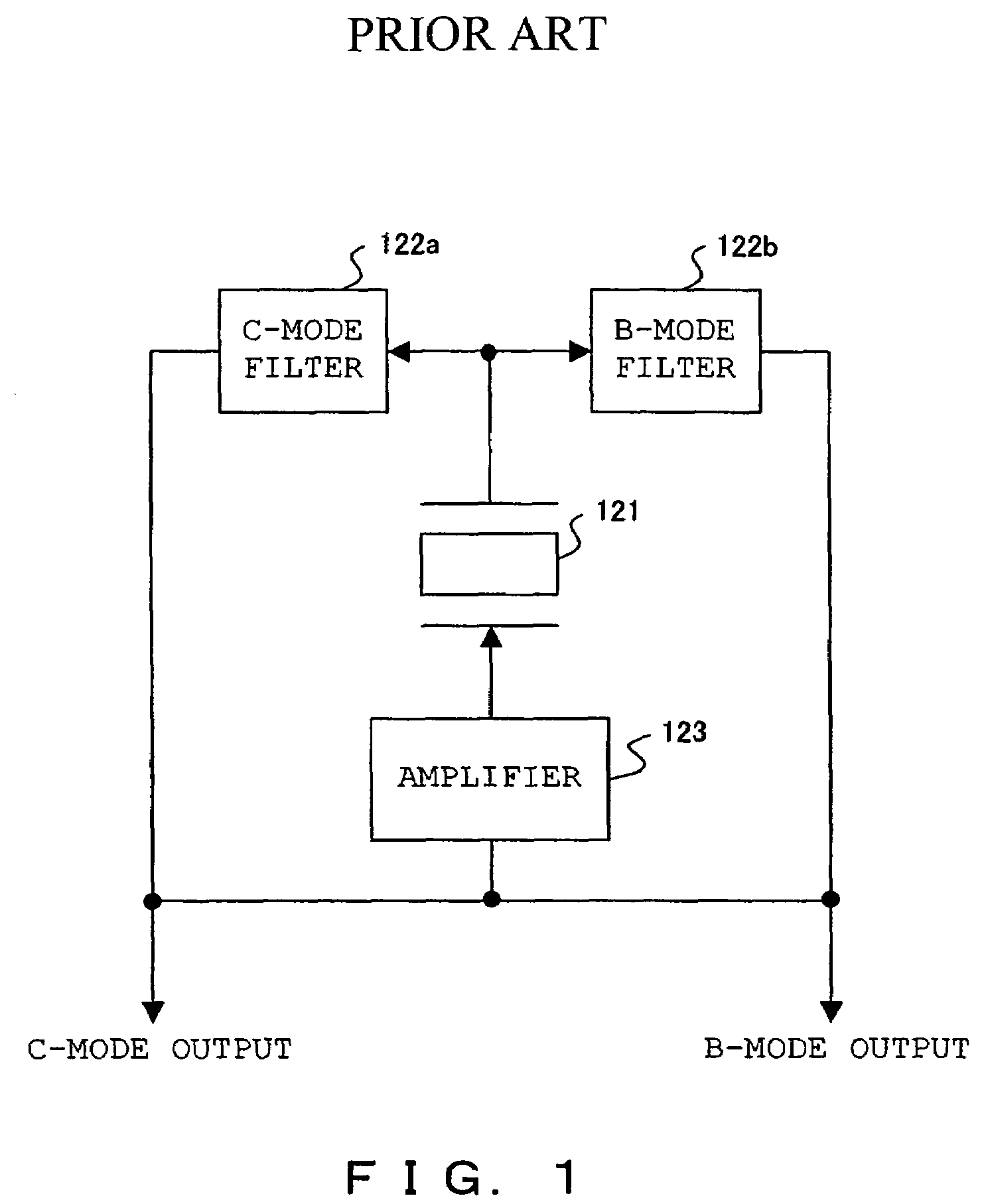
However, none of the Patent Documents 1 to 3 describe the detailed configuration of a circuit to realize the simultaneous generation of two modes.
Especially, in order to unfailingly generate upon power supply, very difficult fine control is required However, none of the Patent Documents above has any description of a means for addressing the see-saw phenomenon.
Therefore with the descriptions of the above Patent Documents, it is difficult to guarantee the stable generation of the signals of two oscillation modes without failure and to maintain the condition as stable as possible.
However, such heaters have a large thermal resistance in the part between the heater and a piece of crystal inside the crystal oscillator package, which is kept at high vacuum, thus thermal efficiency is low and lack long-term stability.
Further the complicated assembly increases cost.

Method used


Image

  • Crystal oscillator device, oscillation method and heater
  • Crystal oscillator device, oscillation method and heater
  • Crystal oscillator device, oscillation method and heater

Examples


second embodiment

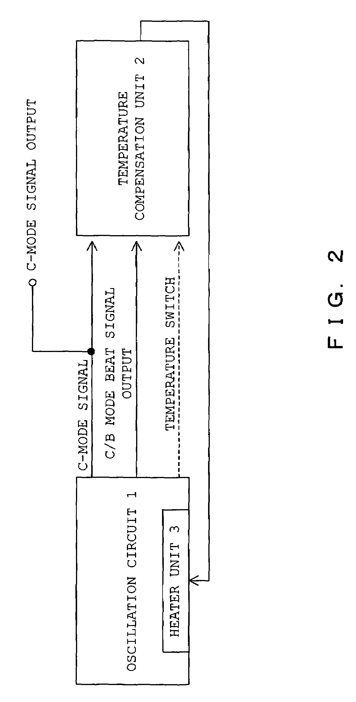
[0100]The following description is an explanation of the temperature compensation unit 2.

[0101]FIG. 7 shows temperature control by the temperature control unit 2.

[0102]In FIG. 7, the target temperature is set at 85° C., and the temperature compensation unit 2 controls the heater based on the C / B mode beat signal of the oscillator circuit 1. When the temperature is controlled from start-up the temperature is low and the resolution of control is low because it takes some time for the temperature to reach the target temperature and the range to be controlled is wide.

[0103]The temperature compensation unit 2 of the second embodiment addresses this problem. The heater is driven at full power from start up until the temperature reaches the predetermined target temperature (85° C. in FIG. 7). When the temperature reaches the predetermined temperature 1 (75° C. in FIG. 7), accurate control of the temperature based on the C / B mode beat signal is performed. As soon as the temperature surpasse...

first embodiment

[0109]When the temperature is between 75° C. and 95° C., H is the output of 75° C. temperature switch and L is the output of 95° C. temperature switch. The output of the adder 515 is input from the AND gate 73 to the OR gate 75, 0 is input from the AND gates 72 and 74, and the output of the adder 515 is input to the pulse width modulator 516. Under these conditions the temperature compensation unit 2 performs control similar to the control shown as in the first embodiment described above, and based on the C / B mode beat signal, and accurate temperature control is achieved.

[0110]FIG. 9 shows a configuration of the temperature compensation unit 2 of the second embodiment.

[0111]In the third embodiment, control similar to the second embodiment is realized without comprising any temperature switch in the oscillator circuit 1.

third embodiment

[0112]The temperature compensation unit 2 of the third embodiment, in addition to the configuration shown in FIG. 6, further comprises configuration elements described in FIG. 9 between the adder 515 and the pulse width modulator 516.

[0113]In the third embodiment, the output of the switch 82 is controlled by a comparator 81 based on the output of the adder 507. The comparator 81 causes the switch 82 to output the maximum value when the temperature, which the C / B mode beat signal in the output S507 of the adder 507 indicates, is lower than 75° C., the output of the adder 515 when it is between 75° C. and 95° C. and the minimum value when it is higher than 95° C. The pulse width modulator 516 drives the heater according to the output of the switch 82.

[0114]Such configuration allows the third embodiment to perform accurate control, in the same way as the second embodiment without the temperature switches in the oscillation circuit 1, by the C / B mode beat signal within the range of 75˜9...


PUM


Abstract

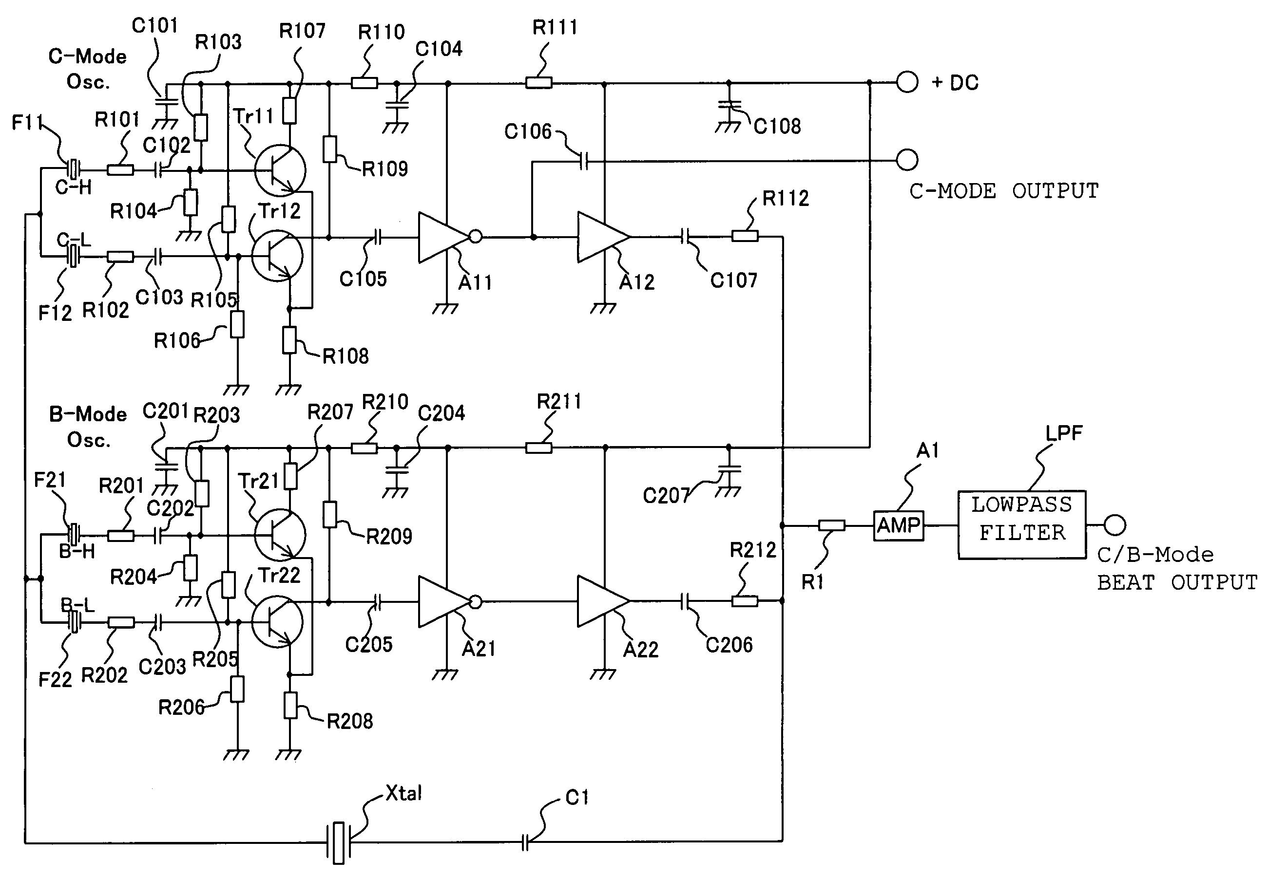
The crystal oscillator device for simultaneously generating oscillator signals with a plurality of oscillation modes of a crystal unit, comprising: a primary resonator unit filtering the oscillator signal with a primary oscillation mode, which is one of the oscillation modes, from the output of the crystal unit, a secondary resonator unit filtering the oscillation signal, bearing a different resonance frequency from that of the primary resonator unit, with the primary oscillation mode from the output of the crystal unit, a primary phase synthesis unit, synthesizing the phases of the output signal of the primary resonator unit and the output signal of the secondary resonator unit, a tertiary resonator unit, a quaternary resonator unit, and a secondary phase synthesis unit.

Description

BACKGROUND OF THE INVENTION[0001]1. Field of the Invention[0002]The present invention relates to an oscillator device utilizing a crystal oscillator, more specifically, to a crystal oscillator device, which can simultaneously generate a plurality of signals with different oscillation modes of the crystal oscillator.[0003]2. Description of the Related Art[0004]The crystal oscillator used in oscillator devices generates not only main oscillation but also sub-oscillation. Generally, only the main oscillation of oscillator devices is utilized, and therefore it is required that the sub-oscillation does not cause deterioration of the main oscillation, this is achieved by controlling the sub-oscillation. However, extraction and utilization of the signal of such a sub-oscillation for the purpose of temperature compensation and so forth have been proposed.[0005]It is widely known that the crystal oscillators such as SC-cut and IT-cut crystal oscillators, for example, generate sub-oscillation...

Claims


Application Information

Patent Timeline
Patent Type & Authority Patents(United States)
IPC IPC(8): H03B5/32H05B3/12H03B5/04H03B5/36
CPCH03B5/04H03B5/366
Inventor OITA, TAKEOFUKUDA, MINORUISHIKAWA, TAKAAKINAKAMURA, AKIHIROONO, KOZOASAMURA, FUMIO
Owner NIHON DEMPA KOGYO CO LTD
Learn More