Antiscattering grid and a method of manufacturing such a grid

a technology of anti-spread grids and grids, which is applied in the field of anti-spread grids, can solve the problems of significant material loss, grids are unable to reduce the degree of radiation scattered in a direction, and reduce the transmission of direct radiation through the grid

Inactive Publication Date: 2008-05-06
GE MEDICAL SYST GLOBAL TECH CO LLC
View PDF16 Cites 5 Cited by
  • Summary
  • Abstract
  • Description
  • Claims
  • Application Information

AI Technical Summary

Benefits of technology

[0017]An embodiment provides a grid that is two dimensional for limiting the filtering of the direct radiation. An embodiment provides an antiscattering grid for radiation, particularly for an X-ray imaging apparatus, of the type comprising a substrate having a plurality of metallized partitions that together define a plurality of cells distributed over the substrate. The partitions allow passage of radiation emitted from a source lying in line with the grid, and absorbing the radiation not coming directly from this source. In an embodiment of the invention the substrate is made of a polymer material. The polymer material is less absorbent of the radiation and therefore permits more of the direct radiation to pass through. This feature permits in particular the reduction of the radiation doses administered to the object.
[0018]In an embodiment the external surfaces of the substrate are not metallized, thereby allowing some of the direct radiation to pass through the substrate. This makes it possible to further increase the quality of the image without increasing the radiation doses administered to the object.
[0019]In an embodiment as the substrate is less absorbent of radiation the gird has less strict dimensioning constraints while still exhibiting superior performance.

Problems solved by technology

A disadvantage for such a grid is that the grid is unable to reduce the degree of radiation scattered in a direction parallel to the plane of the plates.
However, the presence of inter-plate members between the plates reduces the transmission of the direct radiation through the grid.
The disadvantage with the above methods is that they are based on the chemical etching of layers of materials and consequently result in a significant loss of material, and hence high costs.
Moreover, a disadvantage with the antiscattering grids in general is that they mask part of the image receiver and leave their impression on the image obtained.

Method used


Image

  • Antiscattering grid and a method of manufacturing such a grid
  • Antiscattering grid and a method of manufacturing such a grid
  • Antiscattering grid and a method of manufacturing such a grid

Examples


Embodiment Construction

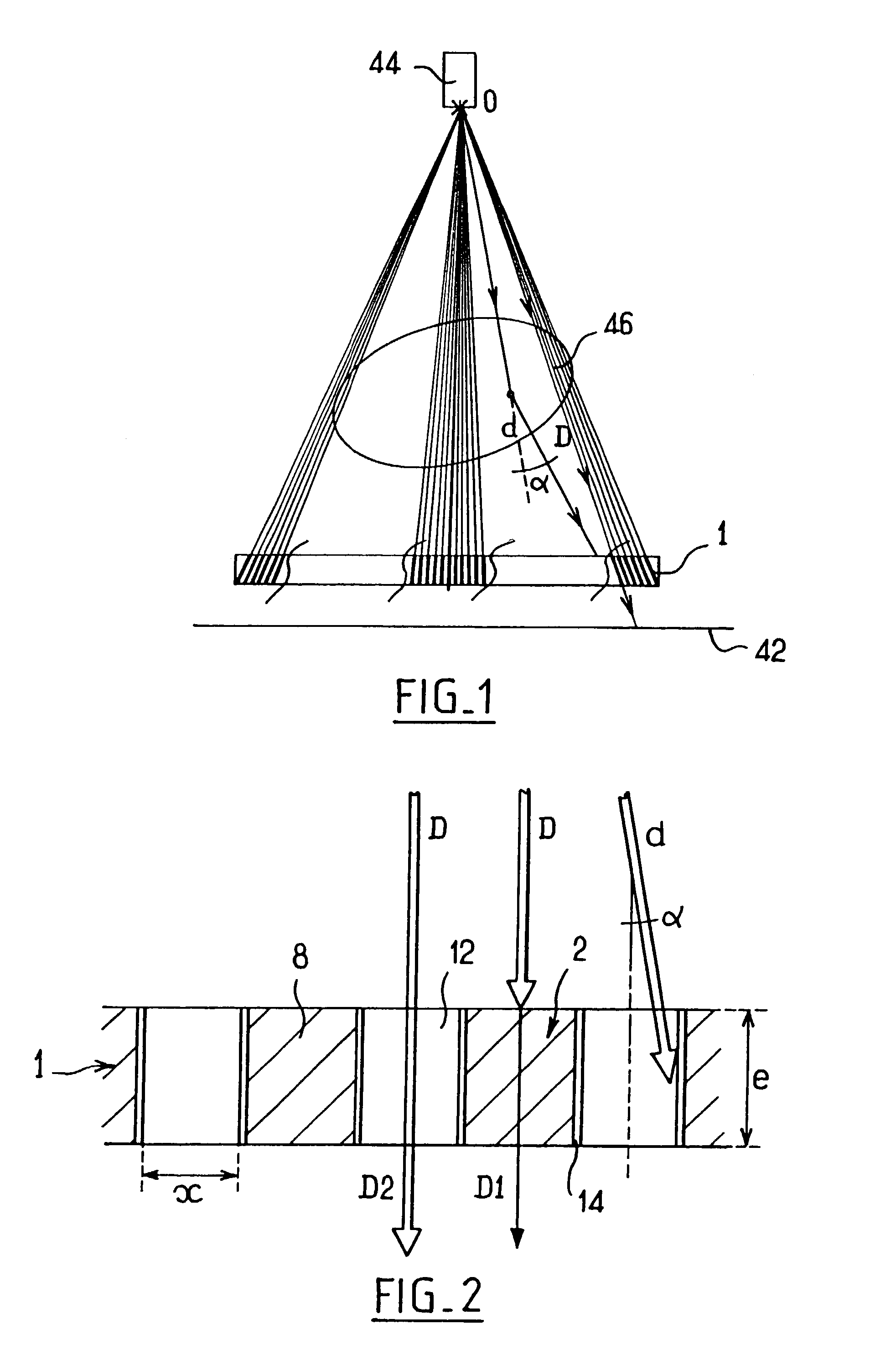
[0031]FIG. 1 shows schematically the principle of operation of an antiscattering grid 1 mounted in a radiology apparatus. The grid 1 is positioned in front of a detector screen 42 so that the radiation source 44 is located at the focal point O of the grid 1. One part of the direct radiation D emitted by the source 44 passes through an object 46, the image of which it is wished to obtain, without undergoing distortion. Another part d of the radiation is scattered by the object 46 so that it strikes the grid at an angle α to the focusing direction of the grid 1. Since the internal partitions of the grid 1 are focused, they absorb the scattered radiation d.

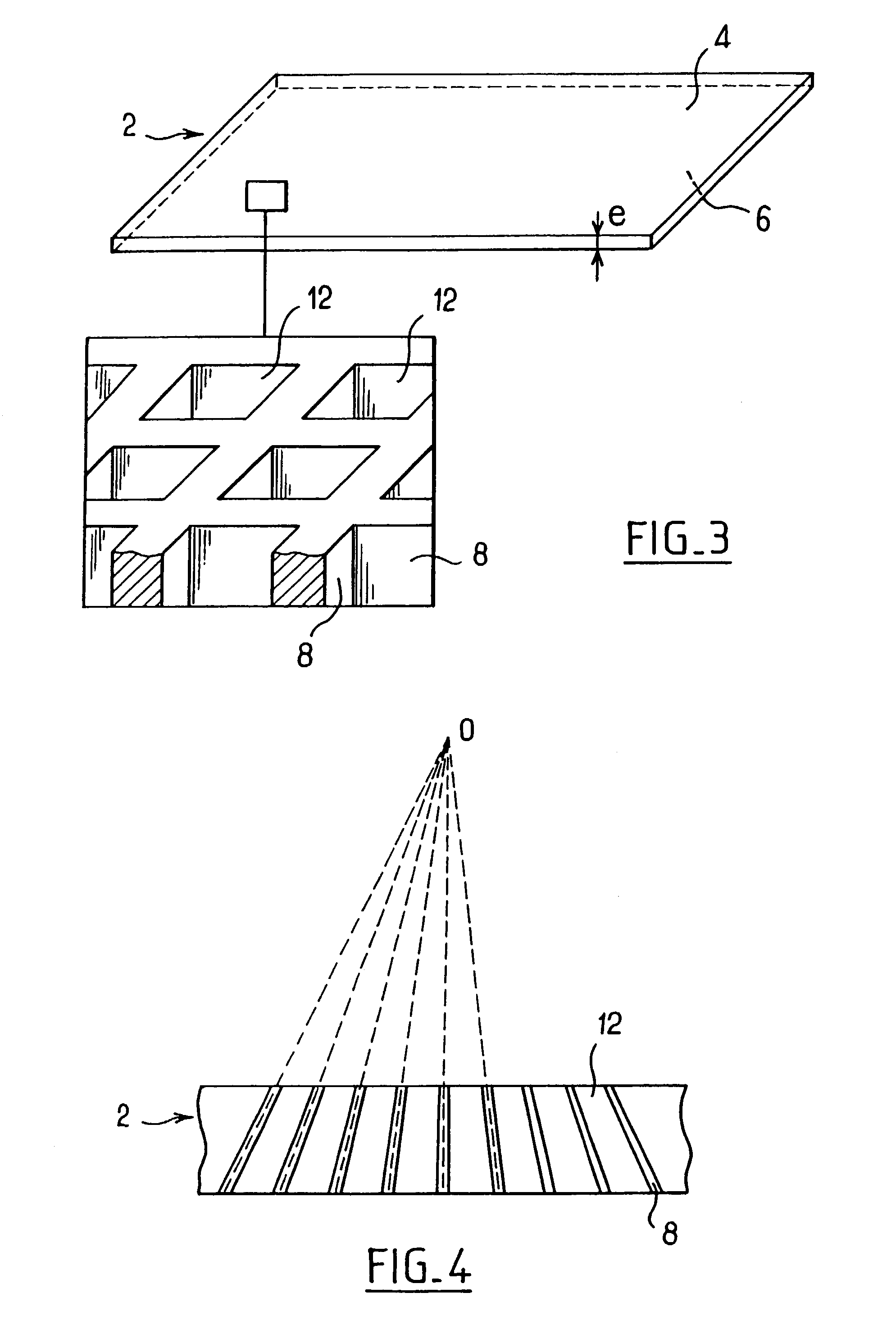
[0032]FIG. 2 shows more specifically the paths of the radiation, during image acquisition, through an antiscattering grid of an embodiment. The grid comprises a substrate 2 made of a polymer material, comprising partitions 8 which define cells 12. The internal walls of the cells 12 are covered with a metal layer 14. A part D1 of the ...


PUM

PropertyMeasurementUnit
thicknessaaaaaaaaaa
thicknessaaaaaaaaaa
thicknessaaaaaaaaaa

Abstract

An antiscattering grid for an X-ray imaging apparatus of the type comprising a substrate having a plurality of metallized partitions that together define a plurality of cells distributed over the substrate. The partitions allow passage of the X-rays emitted from a source lying in line with the grid, and absorbing the X-rays not coming directly from this source. The substrate is made of a polymer material that may be formed by radiation curing of a monomer sensitive to this radiation. The substrate may be substantially planar and the partitions may be oriented to form a focused grid.

Description

CROSS-REFERENCE TO RELATED APPLICATIONS[0001]This application claims the benefit of a priority under, 35 USC 119 to French Patent Application No. 01 13357 filed Oct. 17, 2001, the entire contents of which are hereby incorporated by reference.BACKGROUND OF THE INVENTION[0002]The invention relates to antiscattering grids and particularly to antiscattering grids used in X-ray imaging. A radiology imaging apparatus may comprise an X-ray source and an image receiver between which the object, of which it is wished to produce an image, is positioned. The beam emitted by the source passes through the object before reaching the detector. It is partly absorbed by the internal structure of the object so that the intensity of the beam received by the detector is attenuated. The overall attenuation of the beam after having passed through the object is directly related to the absorption distribution in the object.[0003]The image receiver may comprise an optoelectronic detector or enhancing film / s...

Claims


Application Information

Patent Timeline
Patent Type & Authority Patents(United States)
IPC IPC(8): B05D3/06C08J7/18C23C14/02G21K3/00G21K1/02
CPCG21K1/025B33Y80/00
Inventor SOUCHAY, HENRIKLAUSZ, REMYBACHER, GUILLAUMERICHOU, BRUNO GILLES
Owner GE MEDICAL SYST GLOBAL TECH CO LLC
Why Eureka
Try Eureka