Thin-film transistor
a transistor and thin film technology, applied in the field of thin film transistors, can solve the problems of difficult photolithography technique use, low carrier mobility, and difficult to carry, and achieve the effects of suppressing the diffusion of impurities, high mutual conductance, and high field-effect mobility
- Summary
- Abstract
- Description
- Claims
- Application Information
AI Technical Summary
Benefits of technology
Problems solved by technology
Method used
Image
Examples
embodiment 1
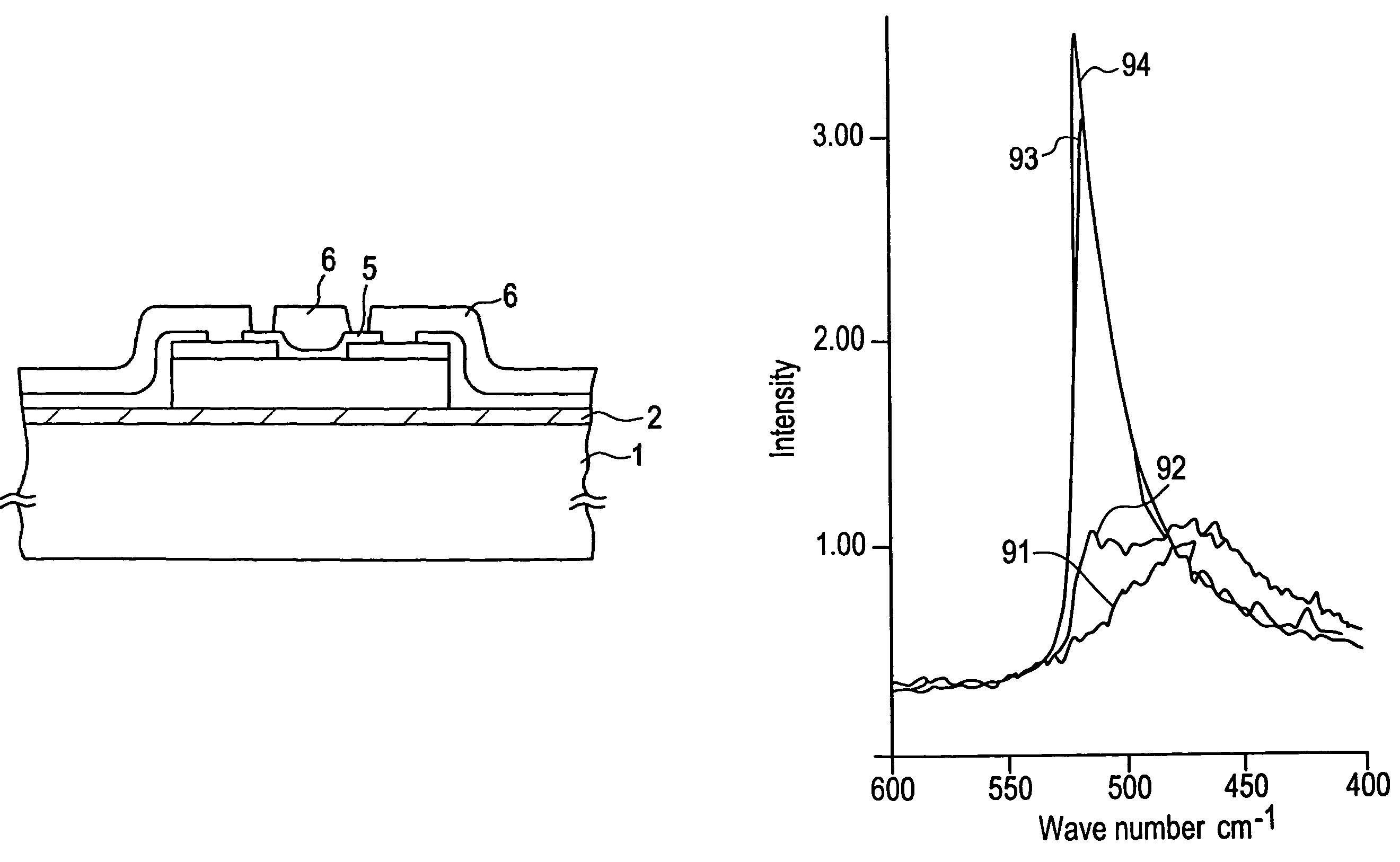
[0035]The manufacturing process of the planar type thin-film transistor in accordance with a first embodiment of the present invention is shown in FIG. 2(A) to FIG. 2(C).
[0036]First a glass substrate 1 is made of soda glass and on an entire surface of the substrate 1, a 300 nm thick silicon oxide bottom protective film 2 is formed by sputtering. The formation conditions of the film are shown below.
[0037]
Sputtering Gasoxygen 100%Reaction Pressure0.5 PaRF Power400 WSubstrate Temperature150° C.Film Formation Speed5 nm / min
[0038]Next, an approximately 100 nm thick I-type conductivity non-single-crystal silicon semiconductor film 3 is formed by a CVD method on the protective film 2. The manufacturing conditions are shown below.
[0039]
Substrate Temperature300° C.Reaction Pressure0.05 TorrRf Power (13.56 MHz)80 WGas UsedSiH4
[0040]After this, a predetermined etching step is. performed, so that the structure shown in FIG. 2(A) is obtained.
[0041]Next, in at least one region of the semiconductor...
embodiment 2
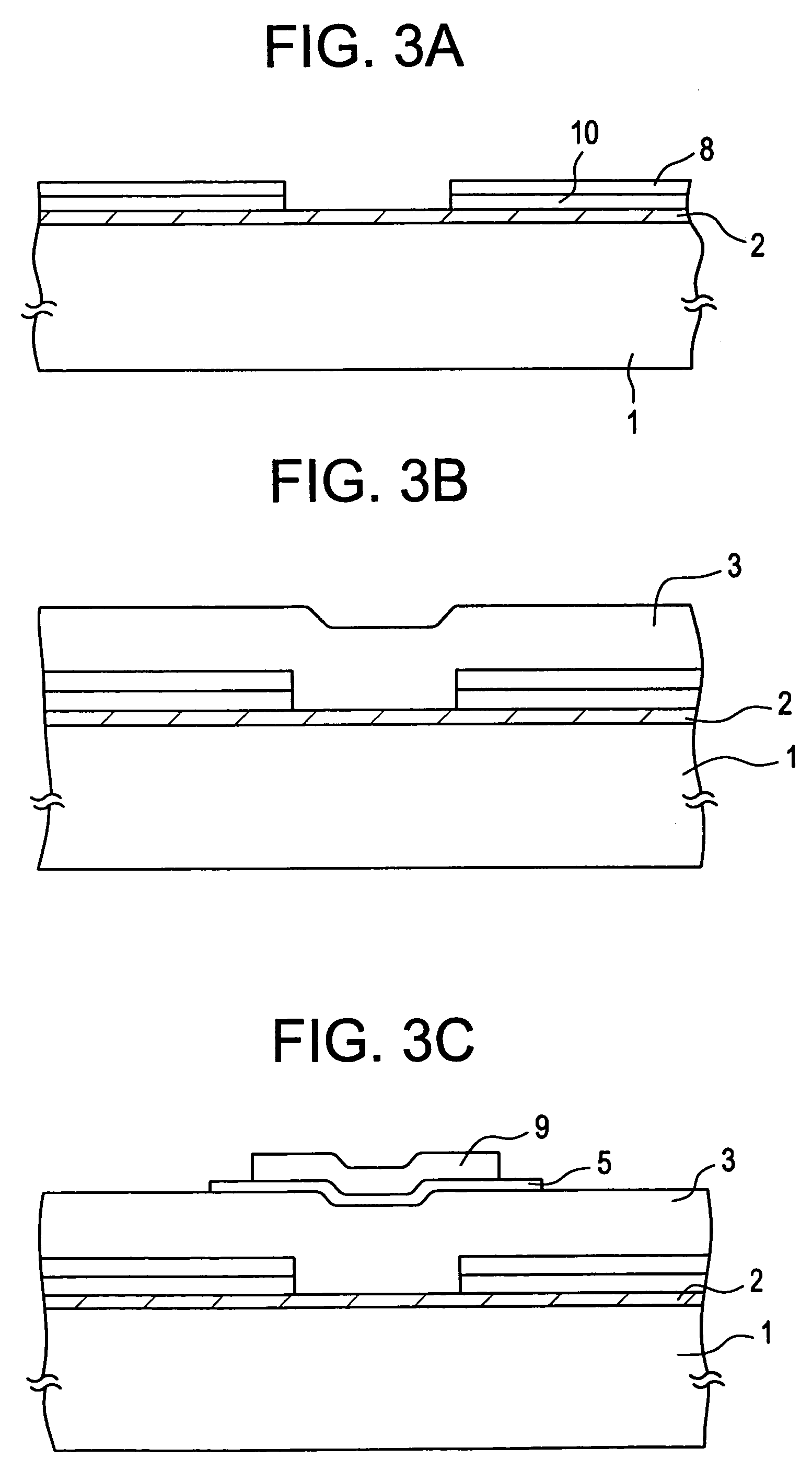
[0051]FIGS. 3A to 3C show a manufacturing process of an IG-FET in accordance with a second embodiment of the present invention. First, a 500 Å to 5000 Å thick silicon oxide film 2 is formed by a sputtering method on top of the soda glass substrate 1 as a protective film in a same manner as in Embodiment 1. Next, on the bottom protective film 2, a 200 nm thick molybdenum metallic layer 10 is formed. Formed on top of this structure is a non-single-crystal silicon film 8 which has a P-type conductor and has a low resistance. The formation conditions this time are as follows.
[0052]
Substrate Temperature230° C.Reaction Pressure0.05 TorrRf Power (13.56 MHz)150 WGas UsedSi4 + B2H6Film Thickness200 Å
[0053]This semiconductor layer can have ohmic contact with the I-type semiconductor layer that will be formed later in the process.
[0054]Next, a predetermined pattern is etched, and the structure shown in FIG. 3(A) is obtained. On top of this structure, a 200 nm thick I-type non-single-crystal si...
embodiment 3
[0060]This embodiment will be explained referring to FIG. 4(A) to FIG. 4(D). In this embodiment a halogen element is added to the protective film on the glass substrate or to the gate insulator of the IG-FET or more preferably to the both.
[0061]In FIG. 4(A) a 200 nm thick SiO2 film 12 is formed on a glass substrate 11 using a magnetron-type RF sputtering method with the following formation conditions.
[0062]
Reaction GasO2 95% volumeNF3 5% volumeFilm Formation Temperature150° C.RF Power (13.56 MHz)400 WPressure0.5 PaSilicon is used as a target.
[0063]On top of this film 12, a 100 nm thick a-Si film 13 is formed by a magnetron RF sputtering in order to form a channel region, so that the structure shown in FIG. 4(A) is obtained. The film formation is done in an atmosphere of inert gas of argon and hydrogen and in the conditions shown below.
H2 / (H2+Ar)=80% (partial pressure ratio)
[0064]
Film Formation Temperature150° C.RF Power (13.56 MHz)400 WTotal Pressur0.5 Pa
Single crystal silicon is us...
PUM
| Property | Measurement | Unit |
|---|---|---|
| temperature | aaaaa | aaaaa |
| length | aaaaa | aaaaa |
| temperature | aaaaa | aaaaa |
Abstract
Description
Claims
Application Information
 - R&D
- Intellectual Property
- Life Sciences
- Materials
- Tech Scout
- Unparalleled Data Quality
- Higher Quality Content
- 60% Fewer Hallucinations
Browse by: Latest US Patents, China's latest patents, Technical Efficacy Thesaurus, Application Domain, Technology Topic, Popular Technical Reports.
© 2025 PatSnap. All rights reserved.Legal|Privacy policy|Modern Slavery Act Transparency Statement|Sitemap|About US| Contact US: help@patsnap.com


