Eureka AIR delivers breakthrough ideas for toughest innovation challenges, trusted by R&D personnel around the world.

Oxygen sensor for aircraft fuel inerting systems

a fuel inerting system and oxygen sensor technology, applied in the direction of instruments, measurement devices, color/spectral properties measurements, etc., can solve the problem of potentially dangerous fuel-air mixtur

Active Publication Date: 2008-04-01
SOUTHWEST SCI
View PDF3 Cites 38 Cited by
  • Summary
  • Abstract
  • Description
  • Claims
  • Application Information

AI Technical Summary

Problems solved by technology

This fuel-air mixture is potentially dangerous if a combustible or explosive composition coupled with favorable environmental factors and an ignition source are present.
Oxygen sensors used in military aircraft are based on zirconium oxide and operate at a high temperature that is not suitable for commercial aircraft due to the potential ignition hazard from the sensor itself.

Method used


Image

  • Oxygen sensor for aircraft fuel inerting systems
  • Oxygen sensor for aircraft fuel inerting systems
  • Oxygen sensor for aircraft fuel inerting systems

Examples


Embodiment Construction

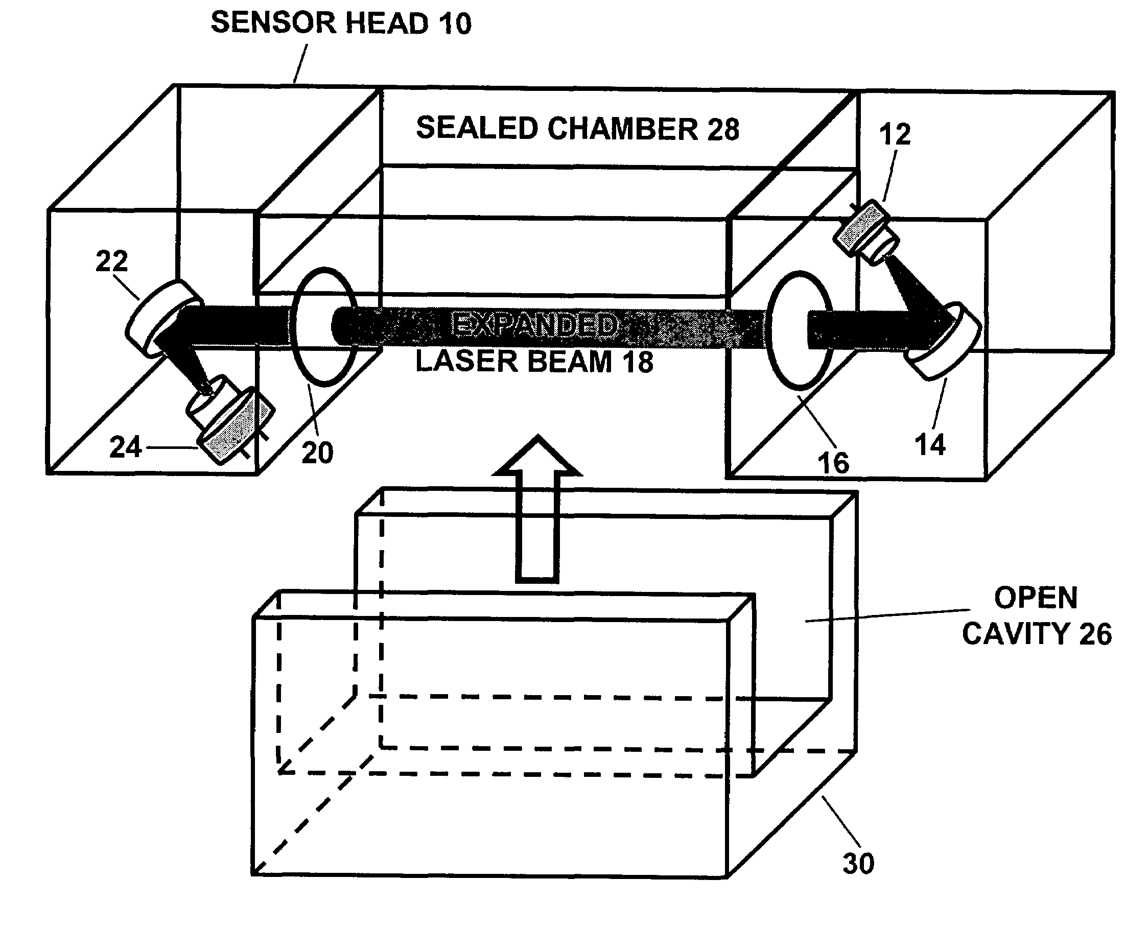
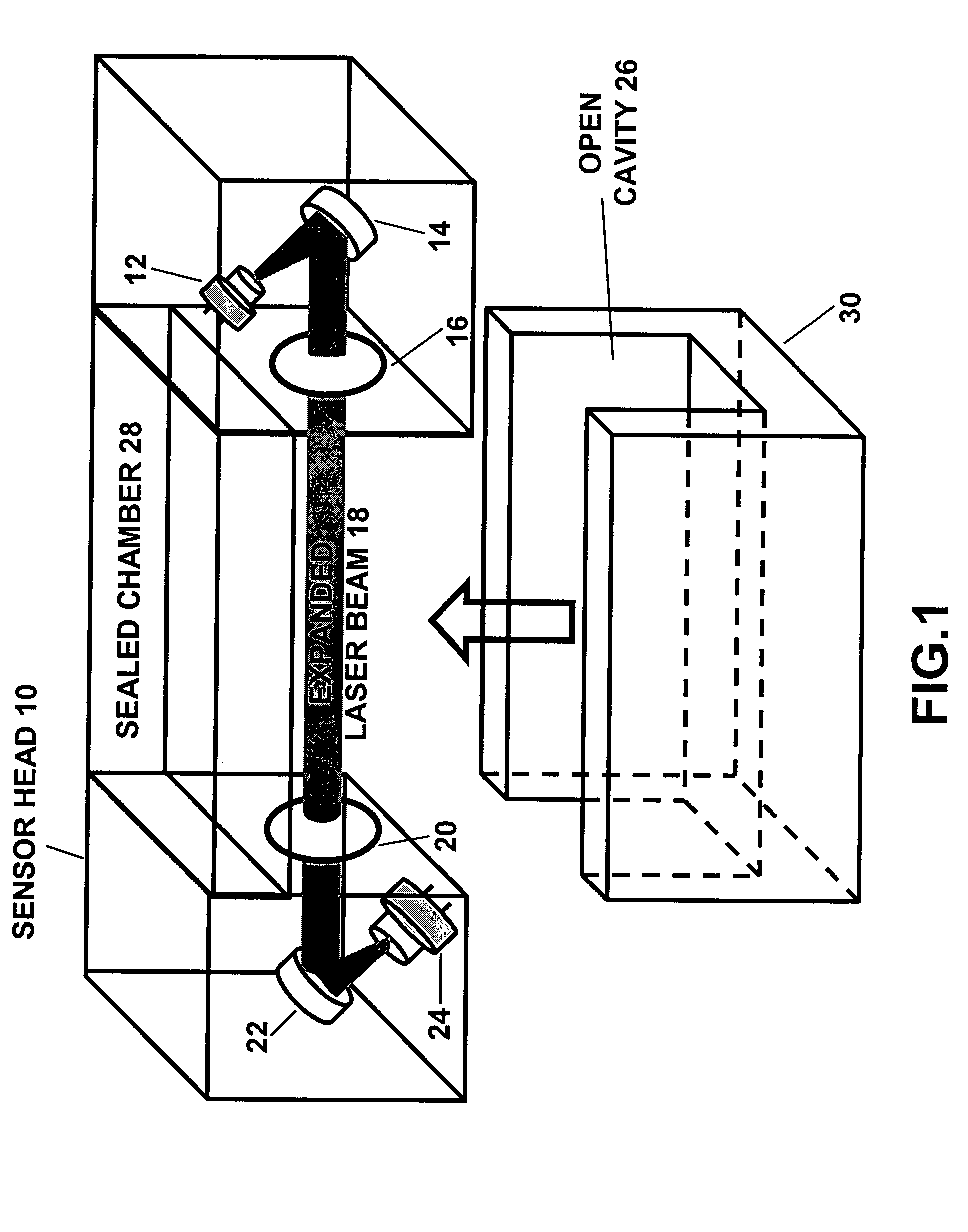
[0024]The present invention is of a sensor system that can continuously monitor oxygen concentrations in aircraft fuel inerting systems which comprise an on-board inert gas generation system and fuel tank. The oxygen sensor system preferably comprises: a sensor head that is inside the fuel tank or in-line with the ASM outlet to monitor oxygen concentrations; an electronics module for controlling the sensor head, acquiring and processing data; and a reporting mechanism for visual and audible warnings to the pilot and a feedback control parameter to the inerting system. The invention can monitor oxygen concentrations inside the ullage of aircraft fuel tanks and / or in-line at the outlet of an air separation module for an onboard inert gas generation system, without the need of a reference cell, with a measurement cavity that is open to the environment being measured, with means to minimize optical degradation due to splashing liquid fuel and liquid droplets depositing on optical window...


PUM

PropertyMeasurementUnit
frequenciesaaaaaaaaaa
wavelengthsaaaaaaaaaa

Abstract

An apparatus and method for monitoring oxygen concentrations in fuel tank ullage comprising providing a sensor head comprising an optical cavity, exposing the optical cavity to an ambient gaseous environment of a fuel tank or air separation module, via a laser light source emitting wavelength modulated light through the cavity, and receiving the wavelength modulated light with a detector.

Description

CROSS-REFERENCE TO RELATED APPLICATIONS[0001]This application claims the benefit of the filing of the following U.S. Provisional Patent Applications: Ser. No. 60 / 534,544, entitled “An oxygen sensor for monitoring the ullage of liquid fuel tanks,” filed on Jan. 5, 2004; Ser. No. 60 / 546,526, entitled “An oxygen sensor for monitoring on-board inert gas generation system and ullage of fuel tanks in aircraft,” filed on Feb. 19, 2004; and Ser. No. 60 / 612,705, entitled “An oxygen sensor for aircraft fuel inerting systems,” filed on Sep. 24, 2004. The specifications thereof are incorporated herein by reference.STATEMENT REGARDING FEDERALLY SPONSORED RESEARCH OR DEVELOPMENT[0002]The U.S. Government has a paid-up license in this invention and the right in limited circumstances to require the patent owner to license others on reasonable terms as provided for by the terms of Grant No. DMI-0319786, awarded by the National Science Foundation.INCORPORATION BY REFERENCE OF MATERIAL SUBMITTED ON A C...

Claims


Application Information

Patent Timeline
Patent Type & Authority Patents(United States)
IPC IPC(8): G01N21/00G01N21/27G01N21/35G01N21/39G01N21/61
CPCG01N21/3504G01N21/39G01N21/031G01N21/274G01N2021/399G01N21/15G01N2021/151
Inventor CHEN, SHIN-JUHSILVER, JOEL A.
Owner SOUTHWEST SCI
Why Eureka
Eureka Blog
Learn More