Demodulation with separate branches for phase and amplitude

a phase and amplitude branch technology, applied in the field of digitally modulated tdma radio signal reception, can solve the problems of reducing receiver sensitivity, difficult to overcome without compromising equalisation performance, and non-coherent detection methods are inherently more noisy than their coherent counterparts

Active Publication Date: 2008-03-25
CADENCE DESIGN SYST INC
View PDF4 Cites 7 Cited by
  • Summary
  • Abstract
  • Description
  • Claims
  • Application Information

AI Technical Summary

Benefits of technology

[0039]It is thus an advantage of the present invention that a wide-dynamic-range radio receiver architecture is provided which is compatible with the requirements of digital, coherent and non-coherent demodulation and equalisation but which avoids the necessity for, and control of, variable gain amplification in the analogue RF section.
[0040]Preferably, the second sequence of samples mentioned above is derived by firstly deriving from said received signal a continuous time signal representative of the instantaneous amplitude or power of the received signal, digitising said continuous time signal and storing the digital samples so generated, determining a reference value of the stored samples over a predetermined time duration, and normalising the stored digital samples utilising the reference value to output the second sequence of samples.
[0041]Preferably this reference value is the peal amplitude or power value in the predetermined time duration.
[0042]In the first embodiment of the invention the first sequence of samples mentioned above is derived by hard limit amplifying the received signal and performing phase detection on the amplified signals to generate a continuous time signal representative of the absolute phase of the received signal and digitising the continuous time signal to output a sequence of samples of the absolute phase of the receive signal as said first sequence of samples.
[0043]In a second embodiment of the invention, the first sequence of samples is derived by hard limit amplifying the receive signal and performing phase detection on the amplified signal to generate a continuous time signal representative of the absolute phase of the receive signal, digitising said continuous time signal to produce a sequence of absolute phase samples, and performing differential phase detection on said sequence of samples to output a sequence of samples each of which characterises the phase shift between pairs of samples of the absolute phase a predetermined number of digitising sample periods apart as said first sequence of samples.

Problems solved by technology

There are, however, two major drawbacks with this approach.
Firstly, non-coherent detection methods are inherently more noisy than their coherent counterparts which reduces receiver sensitivity.
Secondly, most channel equalisation methods rely on the existence of a linear channel between transmitter and demodulator and the differential phase detection process of the non-coherent detector introduces a non-linearly which is difficult to overcome without compromising equalisation performance.
Despite its relative simplicity, this approach has a drawback in fast fading environments where the signal level may vary widely from one frame to the next.
This is a particular problem in TDMA systems which employ slow (or frame rate) frequency hopping.
This can have unacceptable implications for the cost and power consumption of the ADC and, due to the requirement for increased dynamic range in the digital baseband processing, downstream digital demodulation circuits.
The Linear receiver provides the demodulator with a faithful representation of the signal received at the antenna allowing application of all conventional demodulation and equalisation techniques but suffers the disadvantage of needing level sensing and gain control functionality which limits its applicability to slow-fading environments—for which frame-by-frame gain tracking is appropriate—and to TDMA protocols featuring redundant burst headers—where burst-by-burst gain acquisition can be considered.
The Limiting receiver, on the other hand, avoids the gain control issue completely but, due to the loss of signal amplitude information, is inappropriate for use in dispersive, multipath channels requiring equalisation.
This is caused when signals reflect from walls, hills, buildings and high-sided vehicles at different ranges resulting in the creation of echoes of the wanted signal at the receiver.
The echoes can cause a number of undesirable effects, depending upon their amplitude, phase and delay relative to the wanted component of the signal and each other.
This is a big problem for the Limiting receiver which strips off signal envelope (amplitude) information presenting the equaliser with the worst kind of nonlinear channel.
For this reason, equalisation is normally not possible with Limiting receivers.

Method used


Image

  • Demodulation with separate branches for phase and amplitude
  • Demodulation with separate branches for phase and amplitude
  • Demodulation with separate branches for phase and amplitude

Examples


first embodiment

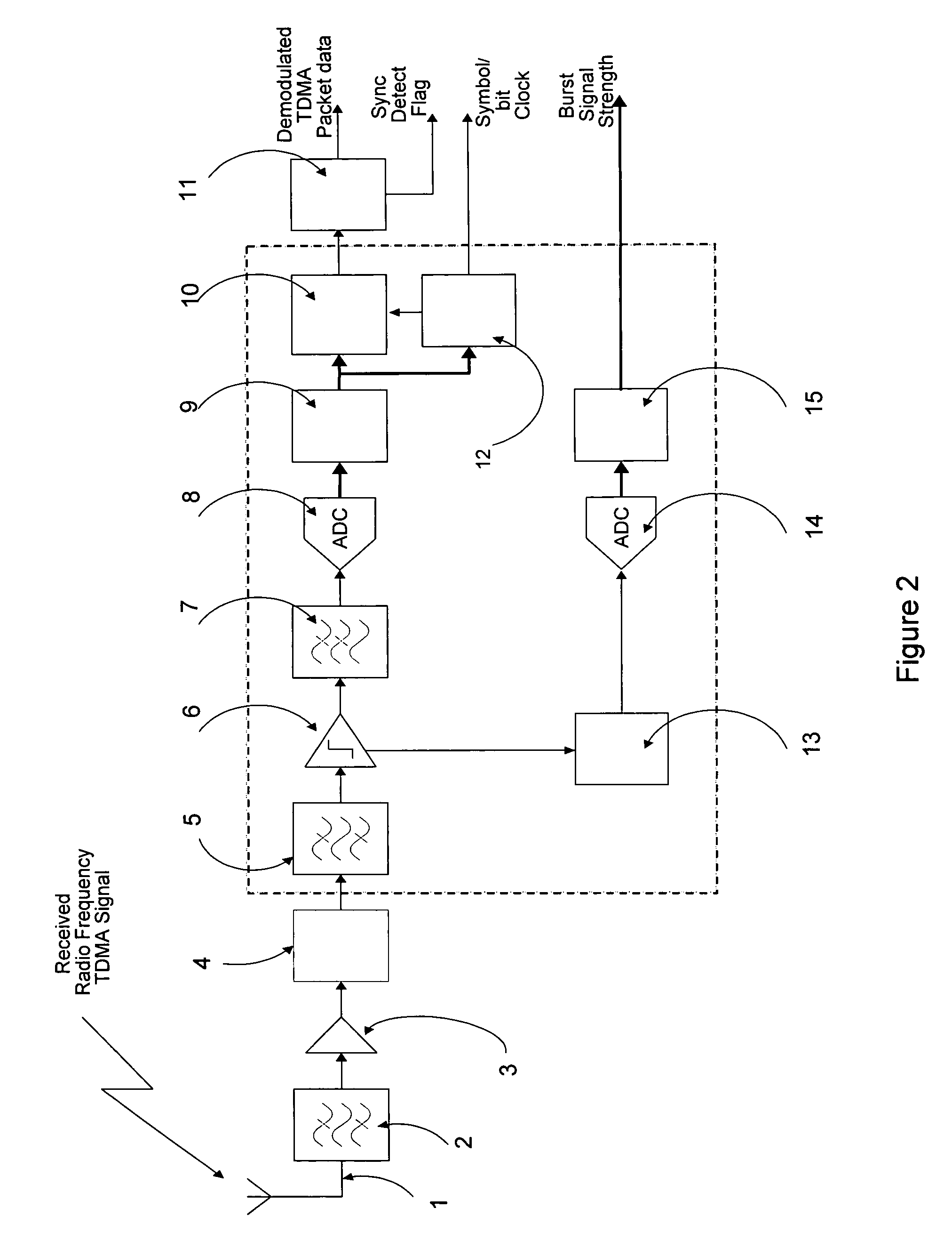
[0080]FIG. 6 shows a receiver in accordance with the present invention. The salient features of this new architecture will now be described in detail.

[0081]A radio frequency TDMA signal is received by antenna 1 which is connected to the chain of filters 2 / 5 / 7, amplifiers 3 / 6 and down-conversion stages 4 which comprise the analogue section of the receiver and which correspond to the like-numbered parts of FIGS. 2 and 3. The pain of amplifier chain 6 is set such that on receipt of a suitably modulated signal, at any arbitrary level within the dynamic range of the radio receiver, the output is driven into saturation (hard-limited) and stripped of its amplitude variations. Accordingly, at the output of amplifier 6 the signal approximates a variable duty cycle square-wave whose absolute phase is defined implicitly by the timings of its high-to-low and low-to-high transitions. Interpolation filter 7 performs time-to-voltage conversion from transitions applied at its input and in so doing ...

second embodiment

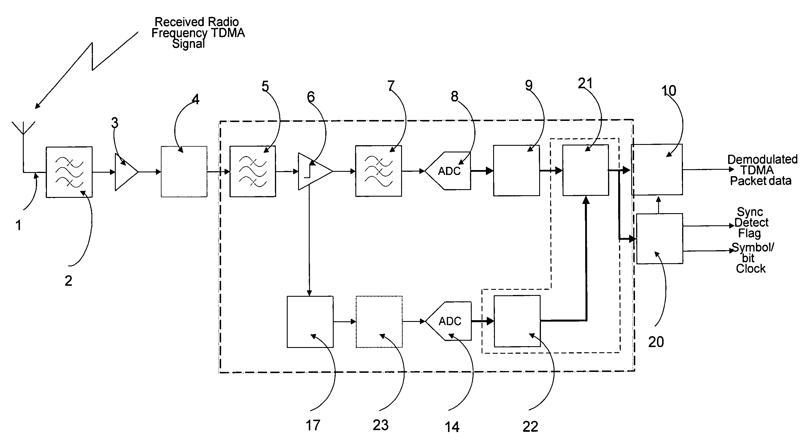
[0085]The Envelope Extractor 22 numerically processes the samples from the Amplitude sequence to derive a new sequence of what are hereafter referred to as Envelope Coefficients. This will be described in detail below, after an outline of the second embodiment has been given.

[0086]FIG. 7 shows a receiver in accordance with the second embodiment of the present invention. The salient features of this new architecture will now be described in detail.

[0087]The analogue section of the receiver is similar to that described previously in FIG. 3. The limiting amplifier block c8 produces a constant-envelope. ‘Phase’ signal component at the output of interpolation filter c9 together with an ‘Amplitude’ signal component at the output of the signal strength detector c15 which has a response time commensurate with channel bandwidth thereby allowing symbol-rate variations in the received signal amplitude to be followed. In known receiver systems, such as depicted in FIGS. 2 and 3, this Amplitude ...


PUM


Abstract

A receiver architecture is disclosed for use in Time-Division Multiple Access (TDMA) and related digital radio applications which combines the principal benefits of the conventional hard-limiting and linear receiver architectures to support switched-antenna diversity and multipath equalisation without the need for receiver gain control. A further feature of the receiver architecture is that minimises the dynamic range needed by the digital signal processing stages thereby reducing complexity, power consumption and cost compared to known arrangements. The (TDMA) radio frequency signal is separated into two components by the analogue section of the receiver: one component characterising the signal's phase, either absolute or differential, the second component characterising the signal's instantaneous magnitude. The (constant-envelope) phase component is digitised by an analogue-to-digital converter (ADC) to form a sequence of phase samples. In a parallel path, the magnitude component is digitised by a second, synchronised ADC, digitally processed to obtain a sequence of coefficients characterising the normalised envelope variations and this is then combined with corresponding (in time) samples of the phase sequence to form a single, composite sequence characterising both the phase and amplitude variations of the received radio frequency signal. This composite sequence is then processed by a digital demodulator / equaliser to recover the transmitted data.

Description

FIELD OF THE INVENTION[0001]The present invention relates generally to the reception of digitally-modulated TDMA radio signals and in particular to those which have passed through a time-varying and dispersive channel. It facilitates the digitisation, normalisation and subsequent demodulation (both coherent and non-coherent) of such signals.BACKGROUND OF THE INVENTION[0002]Digital ‘Cordless’ telephones using Time-Division Multiple Access (TDMA) protocols are now commonplace throughout the world with a range of national and international protocol standards providing a basis for a range of low-cost, low-power products to cater for most short-range office and domestic applications.[0003]In a TDMA communications system, time is divided up into a series of notional, fixed-duration frames which are themselves sub-divided into a number of fixed-duration timeslots. Transmitting equipment samples and temporarily stores user information (which might be speech and / or a digital data stream) and...

Claims


Application Information

Patent Timeline
Patent Type & Authority Patents(United States)
IPC IPC(8): H03D3/00H04J3/00H04L27/38
CPCH04L27/389
Inventor RUDKIN, PAUL
Owner CADENCE DESIGN SYST INC
Why Eureka
Try Eureka