Video information transmission system, and apparatus and program used for video information transmission system
a video information and transmission system technology, applied in television systems, two-way working systems, frequency-division multiplexes, etc., can solve the problems of degradation of reproduction quality, difficulty in smoothly reproducing continuous media, and eminently affecting the quality of reproduction, so as to reduce the quantity of information to be fed, facilitate processing, and effective use of the network
Active Publication Date: 2008-03-11
KDDI CORP
View PDF13 Cites 63 Cited by
- Summary
- Abstract
- Description
- Claims
- Application Information
AI Technical Summary
Benefits of technology
The present invention provides a video information transmission system that can smoothly transmit and reproduce high-quality real-time compressed video information even on a network that is not guaranteed to provide quality of service. The system includes a sender side that controls the transmission of video information based on congestion information from the network, and a receiver side that decides the transmission bit rate based on the congestion information. The congestion information can be measured in terms of network jitter or packet loss rate, and the transmission bit rate can be adjusted accordingly. This allows for effective use of network resources and ensures smooth video transmission.
Problems solved by technology
Due to this, if continuous media such as video or voice information are compression-transmitted and continuously reproduced, the degradation of quality occurs, making it often difficult to smoothly reproduce the continuous media.
As a result, network congestion occurs, packet propagation delay grows and packet loss is induced, so that the degradation of reproduction quality eminently appears on the receiver side.
However, these measures have a disadvantage in that the transmission bit rate is not controlled before packet loss occurs and reproduction quality degrades.
Further, if the packet loss is attributed to buffer overflow at a gateway on the network, the transmission bit rate is increased until the buffer on the network becomes full.
Due to this, these measures have a disadvantage in that delay by as much as the size of the network buffer always occurs.
However, the measures require a mechanism in which each network switch feeds back queue length information, disadvantageously complicating packaging.
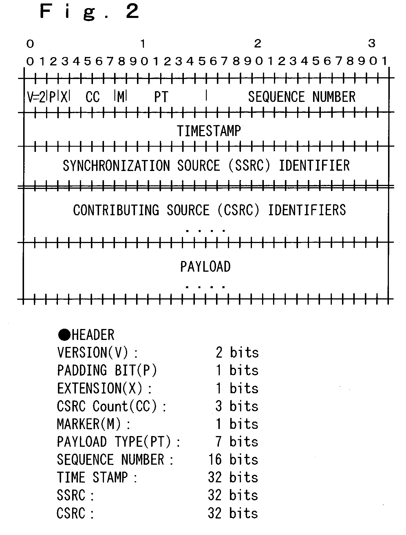
Besides, the measures have a disadvantage in that data transmission cannot be realized using a standard protocol such as RTP (Real-time transport protocol) / RTCP (RTP control protocol) standardized under IETF RFC1889.
However, the measures have disadvantages in that not only the optimum setting of a target buffer value is difficult but also the re-setting of the target value is necessary whenever the bandwidth of the network changes.
Further, the measures have a disadvantage in that if the target buffer value is controlled to be fixed and the network bandwidth narrows by half, for example, delay doubles.
Method used
View moreImage
Smart ImageViewing Examples
Examples
case 1
[0084] a case where extreme congestion occurs;
case 2
[0085] a case where middle-level congestion occurs;
case 3
[0086] a case where slight congestion occurs;
Login to View More PUM
 Abstract
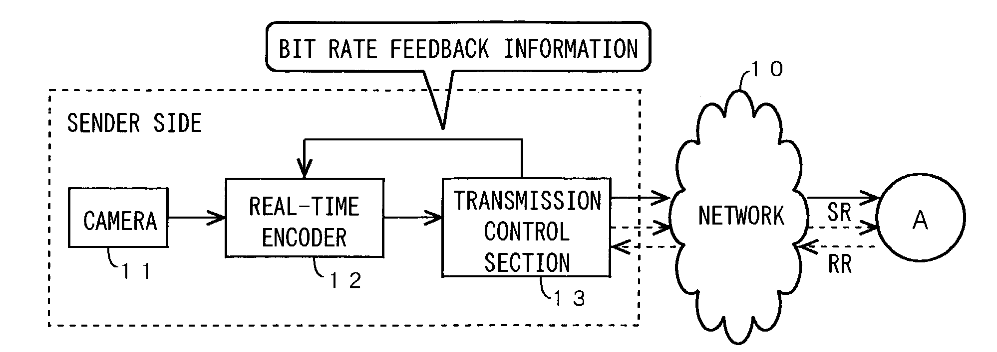
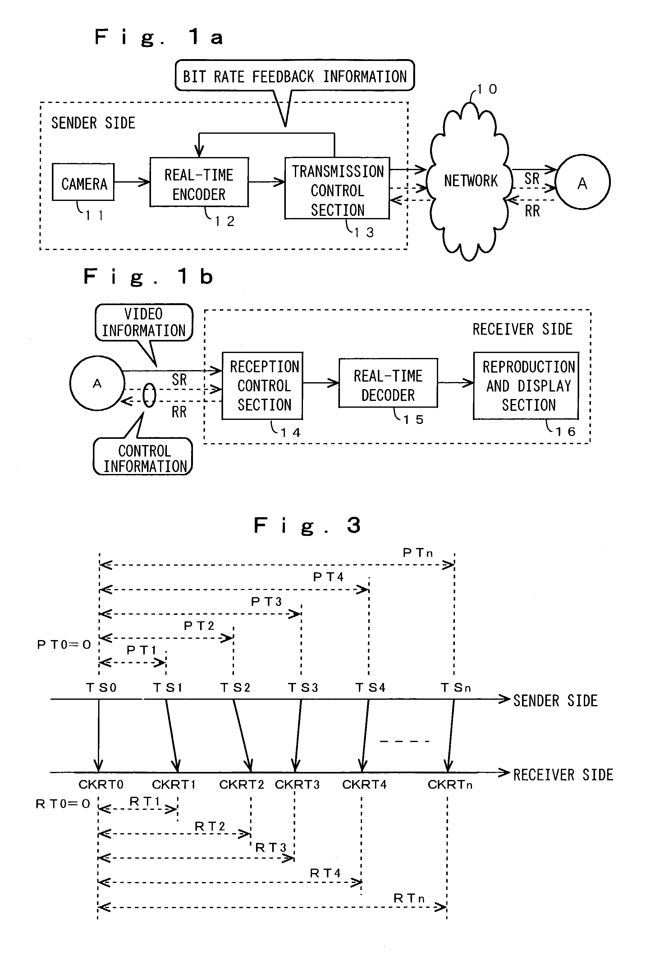
This invention provides a video information transmission apparatus for efficiently transmitting a digital video such as MPEG video at real time while controlling congestion on a QoS non-guaranteed IP network and suppressing degradation of a video quality. A transmission control section 13 on a sender side outputs bit rate feedback information in accordance with congestion information on the network to a real-time encoder 12, and controls a transmission bit rate to change the transmission bit rate in accordance with congestion information on the network. The bit rate feedback information is obtained based on the congestion information on the network on the sender side, or obtained on a receiver side and fed back.
Description
BACKGROUND OF THE INVENTION[0001]1. Field of the Invention[0002]The present invention relates to a video information transmission system, and an apparatus and a program used for the video information transmission system. More specifically, the present invention relates to a video information transmission system, and an apparatus and a program used for the video information transmission system for efficiently transmitting video information such as a live video at real time while suppressing the degradation of video quality by controlling congestion on a network without QoS (Quality of Service) guarantee.[0003]2. Description of the Related Art[0004]On a QoS non-guaranteed IP network such as the Internet, a transmission bandwidth, a transmission error rate, a jitter and the like change with the passage of time. Due to this, if continuous media such as video or voice information are compression-transmitted and continuously reproduced, the degradation of quality occurs, making it often d...
Claims
Login to View More Application Information
Patent Timeline
 Patent Type & Authority Patents(United States)
IPC IPC(8): G01R31/08H04L47/2416H04L47/267H04N7/08H04N7/081H04N7/173H04N7/50H04N19/00H04N19/115H04N19/126H04N19/164H04N19/166H04N19/172H04N19/174H04N19/189H04N19/196H04N19/503H04N19/51H04N19/513H04N19/577H04N19/61H04N19/625H04N19/70H04N19/85H04N19/91H04N21/2343H04N21/24
CPCH04N21/234354H04N21/2402H04N21/6373H04N19/61H04N21/64738H04N21/64769H04N21/658H04N21/6377
Inventor YANAGIHARA, HIROMASAYONEYAMA, AKIONAKAJIMA, YASUYUKI
Owner KDDI CORP
Features
- R&D
- Intellectual Property
- Life Sciences
- Materials
- Tech Scout
- Unparalleled Data Quality
- Higher Quality Content
- 60% Fewer Hallucinations
Learn More Browse by: Latest US Patents, China's latest patents, Technical Efficacy Thesaurus, Application Domain, Technology Topic, Popular Technical Reports.
© 2025 PatSnap. All rights reserved.Legal|Privacy policy|Modern Slavery Act Transparency Statement|Sitemap|About US| Contact US: help@patsnap.com


