Eureka AIR delivers breakthrough ideas for toughest innovation challenges, trusted by R&D personnel around the world.

Ski spot apparatus with integrated force transmission system

a transmission system and ski spot technology, applied in the field of ski sport apparatuses, can solve the problems of poor ski guiding at the front and rear of the ski, poor ski guiding at a high speed, and considerable worsening of running smoothness, so as to achieve good ski guiding, good curve dynamics, and high stability

Inactive Publication Date: 2008-03-11
BUNTER ROLAND
View PDF44 Cites 22 Cited by
  • Summary
  • Abstract
  • Description
  • Claims
  • Application Information

AI Technical Summary

Benefits of technology

[0008]It is one object of this invention to provide a ski which unifies good ski guiding with good curve dynamics and optimizes these without inhibiting these positive characteristics. With a longer ski with a high stability, tighter radii of curvature are to be able to be travelled at a high speed.
[0009]The ski according to this invention is defined in this specification and in the claims and achieves these and other objects. The force introduction of the user or snow sportsman by an interface device which may be integrated above the ski, on the ski or in the ski, is accomplished via at least two outer force introduction regions outside the ski-binding region further to the front or rear, on the ski. The ski in the middle is thinner and / or softer and / or has a lower bending stiffness than a conventional ski. Thus it may bend to a greater extent and more easily, which contributes to good curve dynamics. The ski is thus designed for an active action means for interactive force transmission from the front and rear ski flex to the middle of the ski and vice versa. The ski at the force introduction regions is thick and / or here has a high bending stiffness. Proceeding from the force introduction regions the bending stiffness in both directions of the longitudinal axis of the ski is normally again gradually reduced according to the type of ski. The bending line of the ski is thus actively optimized under the variously acting forces during the travelled curve. The force introduction of the user or snow sportsman onto the ski is effected via the following different variations.
[0019]With the cited force introduction possibilities, on the one hand a larger pressure is produced at the front and rear on the ski, by which an extraordinarily direct ski guiding and a revolutionary grip are produced, and vibrations are better absorbed which provides the ski with an incomparably good running smoothness. The bending stiffness of the ski is reduced in the middle of the ski compared to a conventional ski, by which the ski may bend better. The radius of the curve is thus determined not only by the setting, but also by the bending line of the ski. The more pressure is given, the more the ski is bent and accordingly the radius to be travelled becomes tighter. If the ski guide pressure reinforcement plate is not a unit with the ski, for example is not adhered to the ski or integrated in the ski, the ski, the tighter the curve travelled does not become increasingly harder and does not reach a bending limit. It is thus easy to travel, having extreme curve dynamics which has a positive effect in the carving region.

Problems solved by technology

This means that the ski guiding is poor at the front and at the rear on the ski.
The ski is unstable, the running smoothness is considerably worsened.
In order to prevent a fluttering, the ski is constructed shorter which again leads to a poor guiding of the ski at a high speed.
Longer skis have a good ski guiding and worse curve characteristics, while shorter skis have good curve dynamics and worse ski guiding.

Method used


Image

  • Ski spot apparatus with integrated force transmission system
  • Ski spot apparatus with integrated force transmission system
  • Ski spot apparatus with integrated force transmission system

Examples


Embodiment Construction

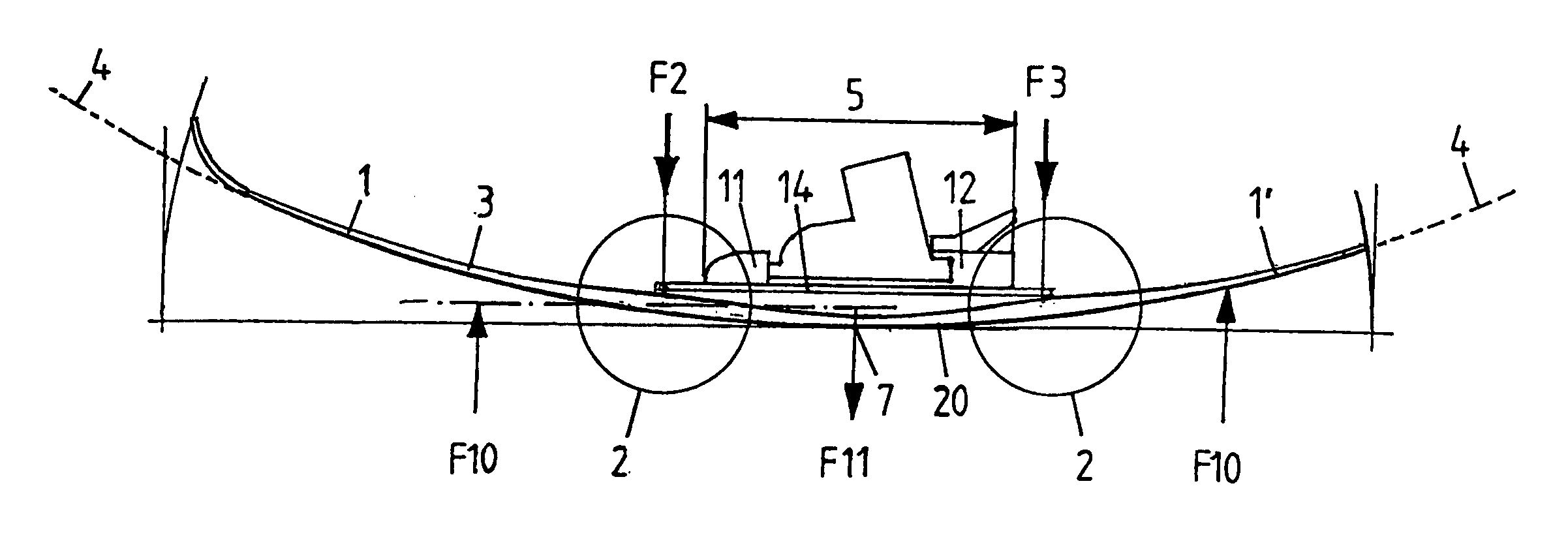
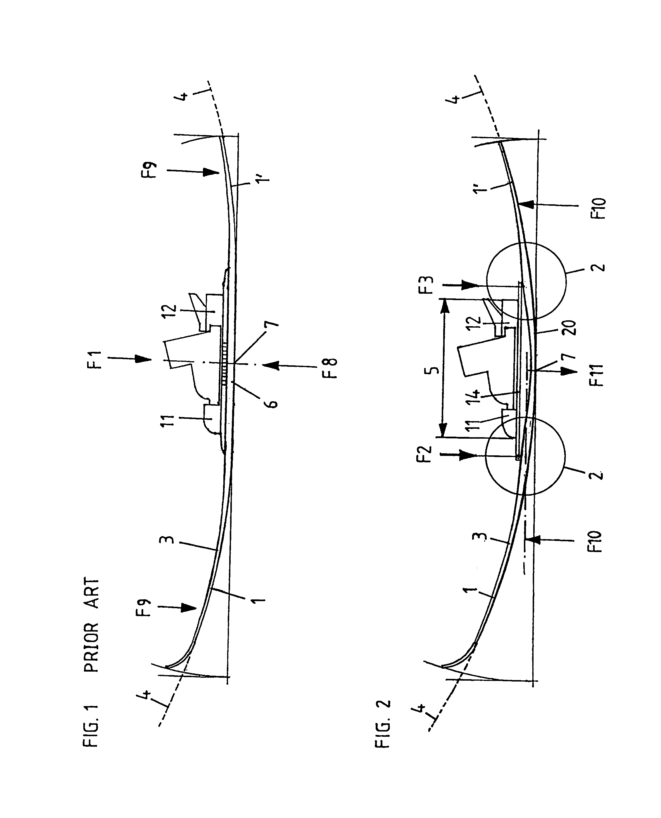
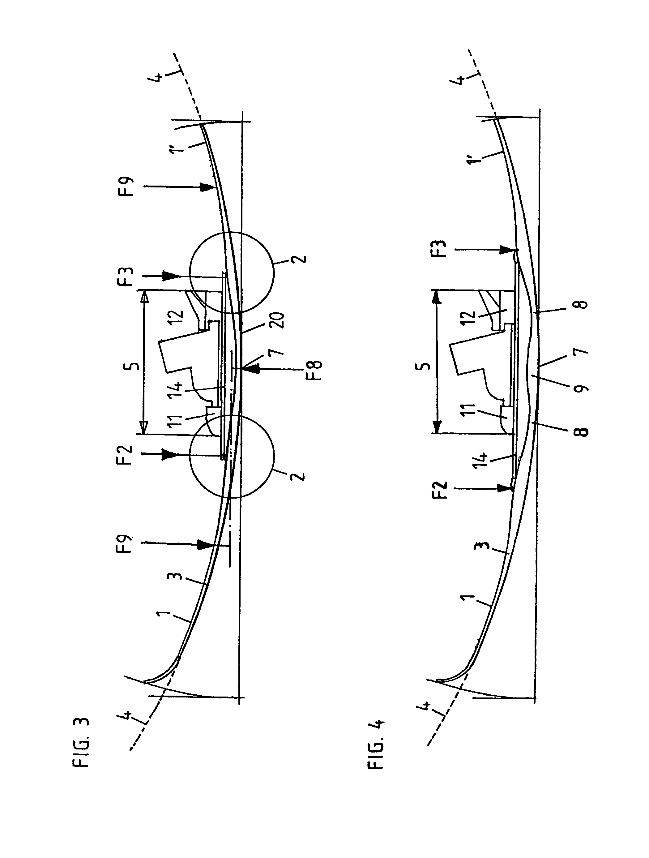
[0027]FIG. 2 shows a preferred embodiment form of a ski 3 according to this invention. The force introduction of the unrepresented user or snow sportsman into the ski 3 is effected via a ski guide pressure reinforcement plate 14 which is fastened on the ski 3, at least two or more force introduction regions F2 and F3 further to the front and rear on the ski. For the sake of simplicity only two force introductions are shown in FIG. 2 but there may be more of these (cf. FIGS. 9, 10, and 12). The ski guide pressure reinforcement plate 14 is assembled onto the ski 3 such that the ski 3 may deflect below the plate 14 and may be easily bent so that the plate 14 acts as a leaf spring. The plate 14 may alternatively also be constructed onto the ski 3 such that the ski 3 and the plate 14 form a unit, or the plate 14 may be integrated in the ski 3, or the plate 14 may be implemented or calculated into the bending stiffness of the ski 3 in the form of a computed force which corresponds to the ...


PUM


Abstract

A ski sport apparatus having a ski with a middle section and two outer sections. An interface device connected to the ski, with a binding region for accommodating a ski binding is arranged in the middle section. The ski sport apparatus has at least two force introduction regions distanced to one another in the longitudinal direction, for introducing forces from the interface device into the ski. The ski in the longitudinal direction has several regions of lower or higher flexibility alternating in the longitudinal direction. The middle section of the ski has a region with a higher flexibility. A frontmost and / or a rearmost force introduction region is allocated to a region with a lower flexibility of the ski and in the longitudinal direction is arranged further to the front or further to the rear than the binding region. The ski has good curve dynamics, has a good ski guiding and excels with an incomparable running smoothness.

Description

CROSS REFERENCE TO RELATED U.S. PATENT APPLICATION[0001]This U.S. Patent Application is a continuation-in-part patent application of U.S. patent application having Ser. No. 09 / 914,275, filed on 15 Jan. 2002, now U.S. Pat. No. 6,648,362 entitled SKI GUIDE PRESSURE INTENSIFIER PLATE (SNOW-SPEED).BACKGROUND OF THE INVENTION[0002]1. Field of the Invention[0003]This invention relates to a ski sport apparatus, snowboards or likewise, in the following generally called “skis”. The ski according to this invention has extremely good curve dynamics, has an extraordinary ski guiding and excels with an incomparable smooth running. The ski according to this invention can maintain tight radii of curvature even with relative tall skiers, with a high stability and a high speed.[0004]2. Discussion of Related Art[0005]A typical conventional ski 3 according to the state of the art is shown in FIG. 1. With a conventional ski 3 the force introduction F1 through the snow sportsman is in the middle 7 of th...

Claims


Application Information

Patent Timeline
Patent Type & Authority Patents(United States)
IPC IPC(8): A63C5/07A63C5/04A63C9/00
CPCA63C5/04A63C5/07A63C9/003A63C9/007
Inventor BUNTER, ROLAND
Owner BUNTER ROLAND
Why Eureka
Eureka Blog
Learn More