Antenna and RFID tag
a technology of rfid tags and antennas, applied in the field of antennas, can solve the problems of difficult to sufficiently increase a bandwidth, the size the complexity of the manufacturing of the rfid tag, so as to increase the frequency bandwidth, increase the bandwidth, and the effect of large bandwidth
- Summary
- Abstract
- Description
- Claims
- Application Information
AI Technical Summary
Benefits of technology
Problems solved by technology
Method used
Image
Examples
first embodiment
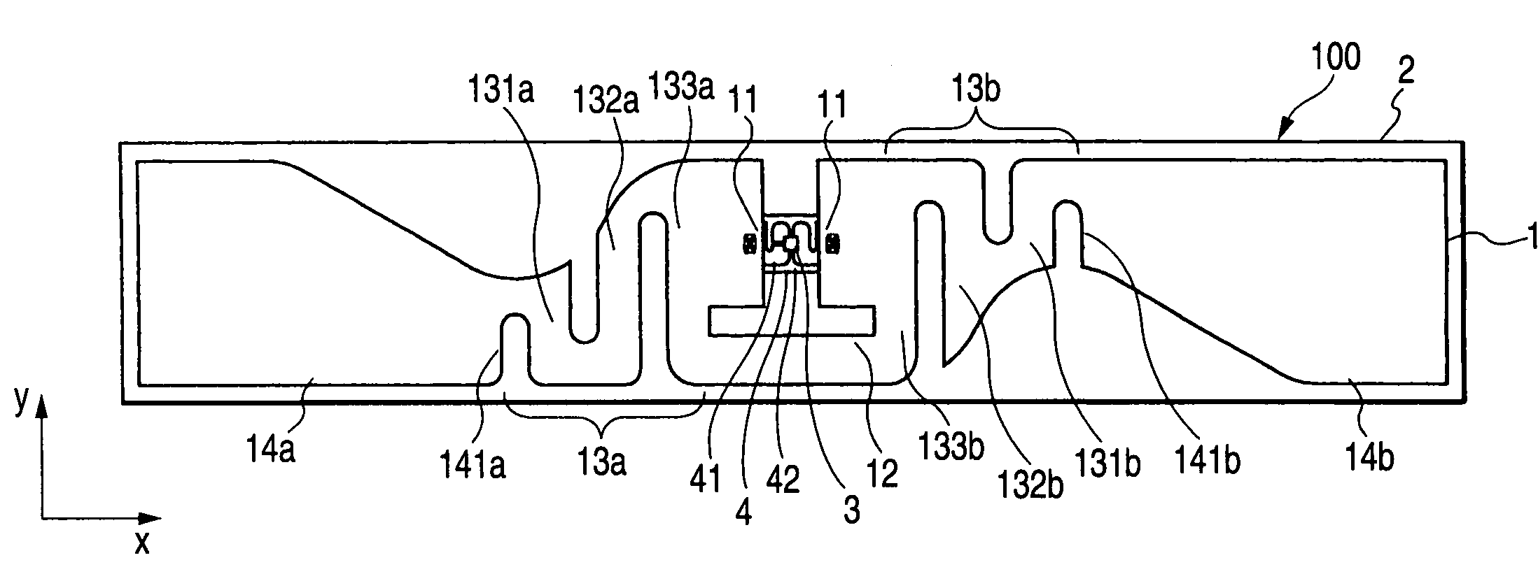
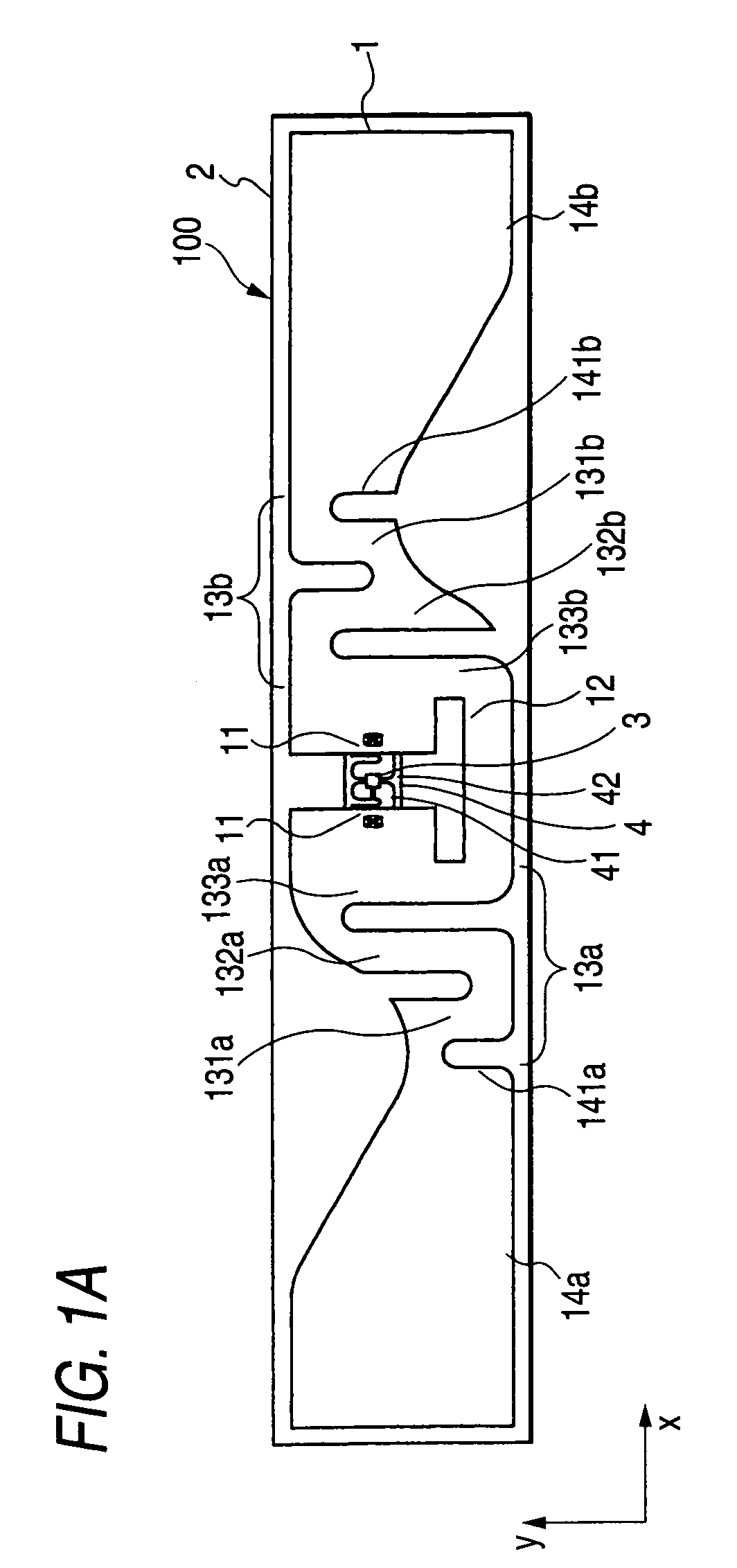
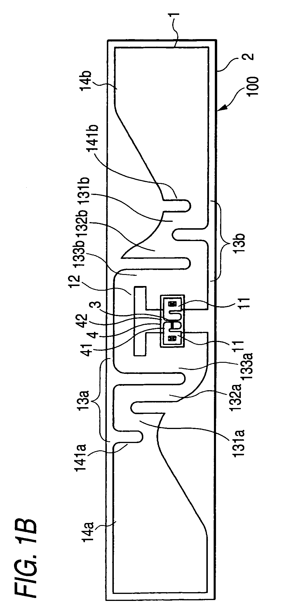
[0039]FIG. 1A is a plan view showing the configuration of an RFID tag according to this embodiment. FIG. 1B is a bottom view showing the configuration of the RFID tag according to this embodiment. FIG. 1C is a front view showing the configuration of the RFID tag according to this embodiment. FIG. 1D is a rear view showing the configuration of the RFID tag according to this embodiment. FIG. 1E is a right side view showing the configuration of the RFID tag according to this embodiment. FIG. 1F is an enlarged view of a portion where a meandering part 13a and a radiating part 14a are connected in the RFID tag according to this embodiment. FIG. 1G is an enlarged view of the vicinity of a portion where a meandering part 13b and a radiating part 14b are connected in the RFID tag according to this embodiment. Further, since a left side view and a right side view are symmetrical, the left side view will be omitted. In the drawings, the RFID tag 100 includes an antenna 1, a dielectric substra...
second embodiment
[0067]An RFID tag according to this embodiment is formed so that the lengths of the sides forming the meandering parts in the direction orthogonal to the longitudinal direction are constant, and the ends of the radiating parts facing the meandering parts are narrower than the widest portions of the radiating parts in the RFID tag 100 according to the first embodiment.
[0068]FIG. 6 is a view showing the configuration of an antenna of the RFID tag according to this embodiment. In FIG. 6, the antenna 20 includes power feeding parts 21, a matching circuit 22, meandering parts 23a and 23b, and radiating parts 14a and 14b. The power feeding parts 21 and the matching circuit 22 have the same configuration as the power feeding parts 11 and the matching circuit 12 of the antenna 1 according to the first embodiment. Accordingly, the description thereof will be omitted. In addition, the meandering parts 23a and 23b have the same configuration as the meandering part 13a and 13b according to the ...
third embodiment
[0071]An RFID tag according to this embodiment is formed so that the lengths of the sides forming the meandering parts in the direction orthogonal to the longitudinal direction are constant, and the ends of the radiating parts facing the meandering parts decrease as coming close to the meandering parts in the RFID tag according to the first embodiment.
[0072]FIG. 7 is a view showing the configuration of an antenna of the RFID tag according to this embodiment. In FIG. 7, the antenna 30 includes power feeding parts 31, a matching circuit 32, meandering parts 33a and 33b, and radiating parts 34a and 34b. The power feeding parts 31 and the matching circuit 32 have the same configuration as the power feeding parts 11 and the matching circuit 12 of the antenna 1 according to the first embodiment. Accordingly, the description thereof will be omitted. In addition, the meandering parts 33a and 33b have the same configuration as the meandering parts 13a and 13b according to the first embodimen...
PUM
 Abstract
Description
Claims
Application Information
 - R&D
- Intellectual Property
- Life Sciences
- Materials
- Tech Scout
- Unparalleled Data Quality
- Higher Quality Content
- 60% Fewer Hallucinations
Browse by: Latest US Patents, China's latest patents, Technical Efficacy Thesaurus, Application Domain, Technology Topic, Popular Technical Reports.
© 2025 PatSnap. All rights reserved.Legal|Privacy policy|Modern Slavery Act Transparency Statement|Sitemap|About US| Contact US: help@patsnap.com


