
Endoluminal cardiac and venous valve prostheses and methods of manufacture and delivery thereof

a technology of endoluminal and venous valve, which is applied in the field of implantable prosthetic cardiac and venous valve implants, can solve the problems of significant hemodynamic, delivery, fatigue and stability disadvantages of devices, and clinically ineffective devices as minimally invasive techniques,

Inactive Publication Date: 2008-03-04
VACTRONIX SCI LLC
View PDF40 Cites 365 Cited by
  • Summary
  • Abstract
  • Description
  • Claims
  • Application Information

AI Technical Summary

Benefits of technology

The solution enables orthotopic delivery of prosthetic valves with improved hemodynamic performance, reduced metal content, and compliance with anatomical structures, eliminating the need for chronic anticoagulation and facilitating atraumatic, minimally invasive procedures with a delivery profile suitable for peripheral vascular applications.

Problems solved by technology

The device presents significant hemodynamic, delivery, fatigue and stability disadvantages.
Specifically, the device and method put forth will require a 20+ French size catheter (approximately 9 French sizes to accommodate the balloon and 14+ French sizes to accommodate the compressed device) making the device clinically ineffective as a minimally invasive technique.
Additionally, the device does not adequately address hemodynamic, stability and anchoring concerns.
The disadvantages of the device are the flow regulators reduce the effective valve orifice and generate sub-optimal hemodynamic characteristics; fatigue concerns arise from the separate nature of the stent and flow-regulation components; the high metal and exposed metal content raises thrombogenesis, valvular stenosis and chronic anticoagulation concerns; and the separate delivery requirements (although addressing the need for small delivery profile) in addition to any initial valvuloplasty performed increases the time, costs, risks, difficulty and trauma associated with the percutaneous procedure.
The disadvantages of the device include large delivery profile, reduced effective valvular orifice, possible perivalvular leakage, trauma-inducing turbulent flow generated by the cage occlusive apparatus and valve seat, thrombogenesis, valvular stenosis, chronic anticoagulation, problematic physiological and procedural concerns due to the barb anchors and complex delivery procedure that includes inflation of occlusive member after initial implantation.
The devices disclosed indicate a long and complex procedure requiring large diameter catheters.
The valve device disclosed will require a large delivery catheter and does not address the key mechanisms required of a functioning valve.
The main disadvantage to this design is the 20+ French size delivery requirement.
Other problems include anchoring stability, perivalvular leakage, difficult manufacture and suspect valve performance.
The disadvantages of this design include lack of sufficient anchoring mechanism; problematic interference concerns with adjacent tissues and anatomical structures; fatigue concerns associated with the multiplicity of segments, connections and sutures; lack of an adequately controlled and biased flow-regulation mechanism; uncertain effective valve orifice, difficult manufacture; balloon dilation requirement; complex, difficult and inaccurate delivery and large delivery profile.
The disadvantages of the device are lack of a well defined and biased flow-regulation mechanism, anatomic valve removal is required thereby lengthening the procedure time, increasing difficulty and reducing clinical practicality, trauma-inducing barbs as described above and the device is unstable and prone to migration if barbs are omitted.
The disadvantages of this design include problematic interactions between the stent and flaps in the delivery state, lack of clinical data on coiled stent performance, the lack of a detailed mechanism to ensure that the flaps will create a competent one-directional valve, lack of appropriate anchoring means, and the design requirements imposed by surrounding anatomical structures are ignored.
The disadvantages of the device include the flow-regulation mechanism provides a small effective valve orifice, the turbidity caused by the multiple slit mechanisms, the large delivery profile required by the disclosed embodiments and the lack of acute anchoring means.
Disadvantages of this device include those profile concerns associated with biological valves and unsupported graft-leaflet regulators, a large diameter complex delivery system and method which requires multiple anchoring balloons and the use of a light activated tissue adhesive in addition to any prior valvuloplasty performed, interference with surrounding anatomy and the questionable clinical utility and feasibility of the light actuated anchoring means.

Method used


Image

  • Endoluminal cardiac and venous valve prostheses and methods of manufacture and delivery thereof
  • Endoluminal cardiac and venous valve prostheses and methods of manufacture and delivery thereof
  • Endoluminal cardiac and venous valve prostheses and methods of manufacture and delivery thereof

Examples


Embodiment Construction

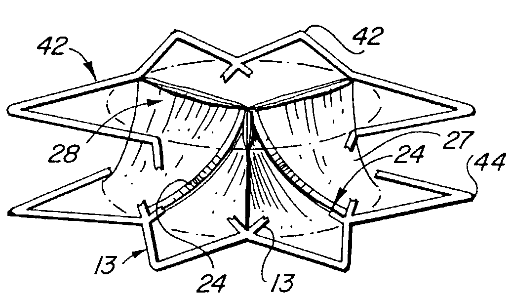
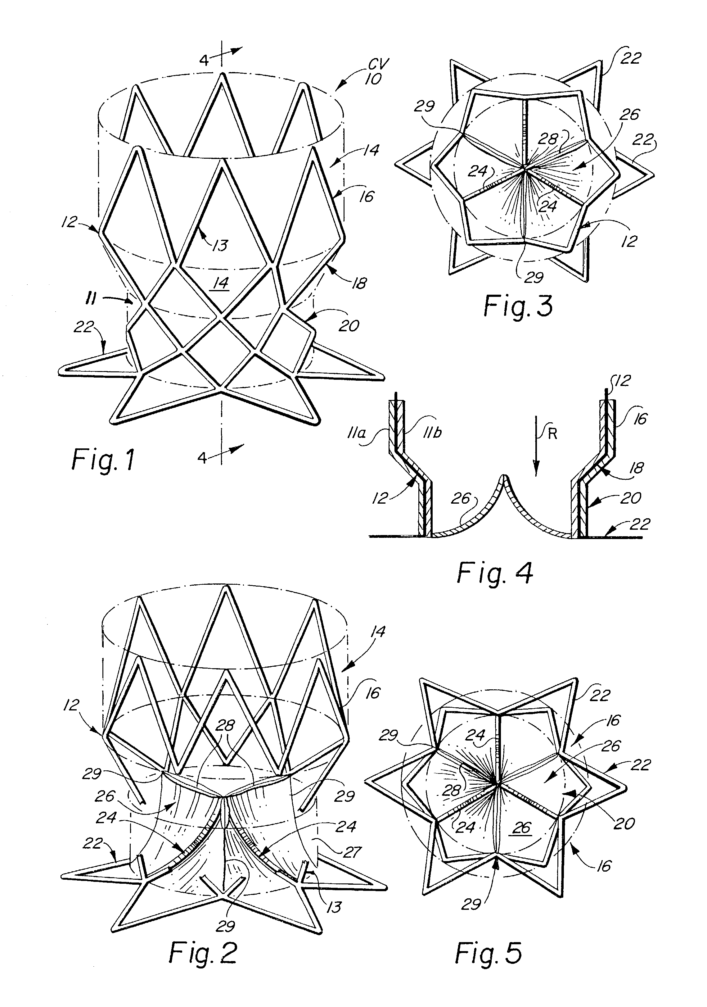
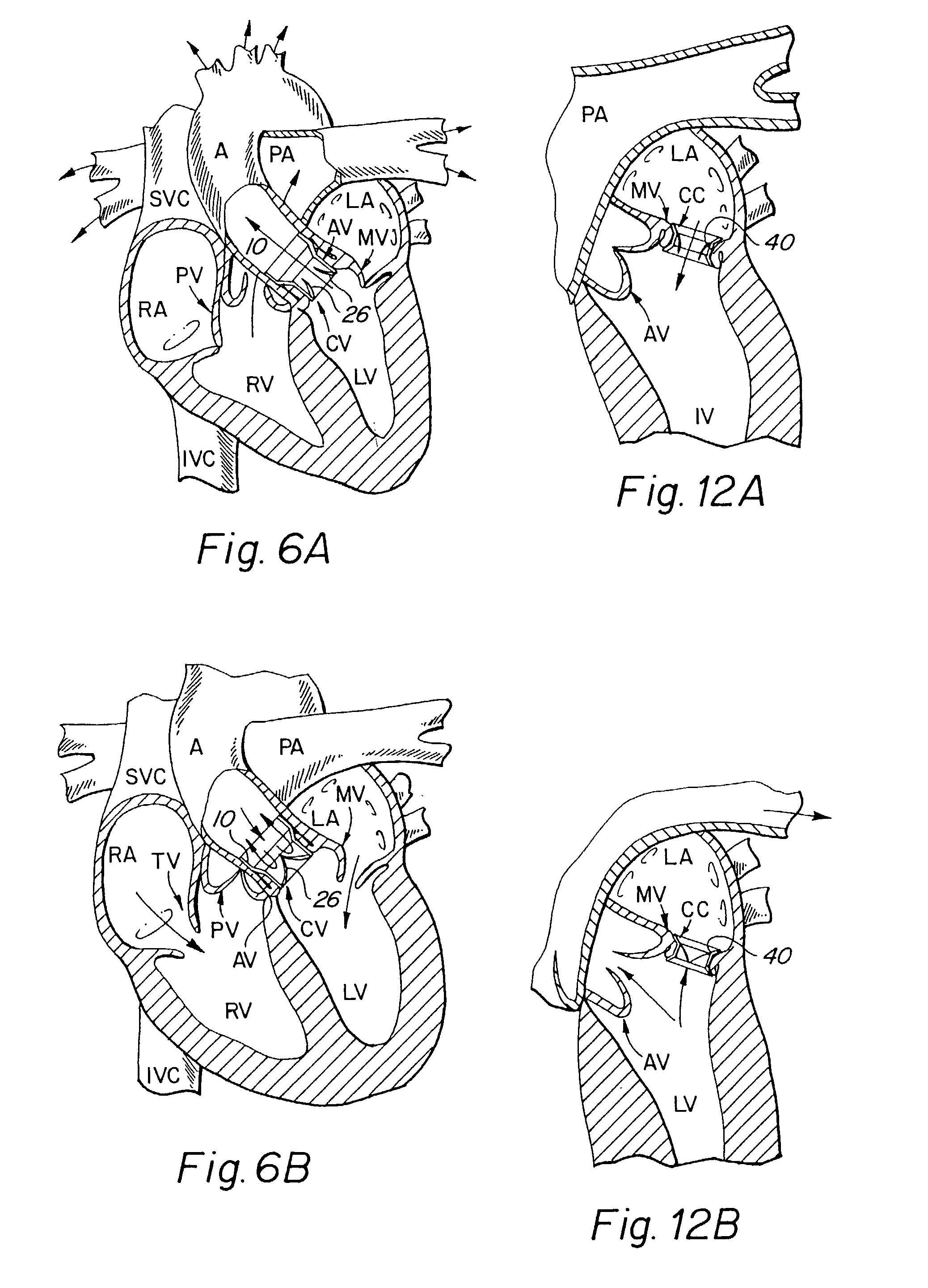
[0046]The present invention consists generally of three preferred embodiments, each embodiment corresponding to a prosthetic stent valve configuration adapted for either heart chamber to blood vessel communication, chamber to chamber communication or vessel to vessel, or intravascular configuration. Certain elements are common to each of the preferred embodiments of the invention, specifically, each embodiment includes a stent body member which defines a central annular opening along the longitudinal axis of the stent body member, a graft member which covers at least a portion of the stent body member along either the lumenal or ablumenal surfaces of the stent body member, at least one biasing arm is provided and projects from the stent body member and into the central annular opening of the stent body member, and at least one valve flap member which is coupled to each biasing arm such that the biasing arm biases the valve flap member to occlude the central annular opening of the st...


PUM


Abstract

This invention relates to prosthetic cardiac and venous valves and a single catheter device and minimally invasive techniques for percutaneous and transluminal valvuloplasty and prosthetic valve implantation.

Description

CROSS REFERENCES TO RELATED APPLICATIONS[0001]This application is a divisional patent application of application, Ser. No. 09 / 477,120 which was filed with the U.S. Patent and Trademark Office on Dec. 31, 1999, now U.S. Pat. No. 6,458,153.BACKGROUND OF THE INVENTION[0002]The present invention relates generally to implantable prosthetic cardiac and venous valves. More particularly, the present invention pertains to prosthetic cardiac and venous valve implants which are capable of being delivered using endovascular techniques and being implanted at an intracardiac or intravenous site without the need for anatomic valve removal. The prosthetic valves of the present invention are well-suited for cardiac delivery via a femoral or subclavian artery approach using a delivery catheter, and, depending upon the specific configuration selected, may be deployed within the heart to repair valve defects or disease or septal defects or disease. According to one embodiment of the invention, there is...

Claims


Application Information

Patent Timeline
Patent Type & Authority Patents(United States)
IPC IPC(8): A61F2/06A61F2/24A61F2/82A61F2/90
CPCA61F2/2418A61F2/2475A61F2220/0008A61F2230/0078A61F2230/005A61F2230/0054A61F2220/0016A61F2/958A61F2/9522A61F2/07A61F2/2412A61F2/243A61F2/2436A61F2/2469
Inventor BAILEY, STEVEN R.BOYLE, CHRISTOPHER T.
Owner VACTRONIX SCI LLC
Learn More