Tilt focus mechanism for an optical drive
a technology of optical drives and focus mechanisms, applied in the direction of instruments, disposition/mounting of heads, maintaining head carrier alignment, etc., can solve the problems of linear actuators with relatively high friction devices, linear actuators are relatively high-friction devices, and require precise track alignmen
- Summary
- Abstract
- Description
- Claims
- Application Information
AI Technical Summary
Benefits of technology
Problems solved by technology
Method used
Image
Examples
first embodiment
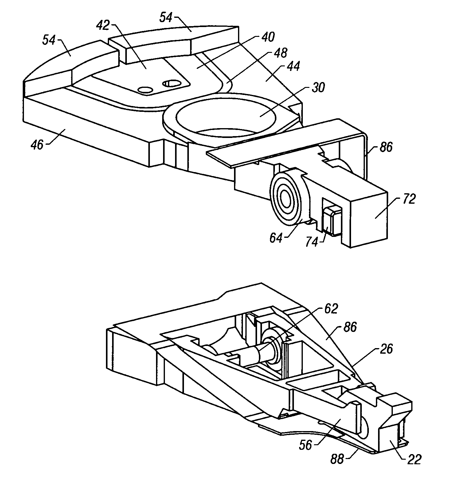
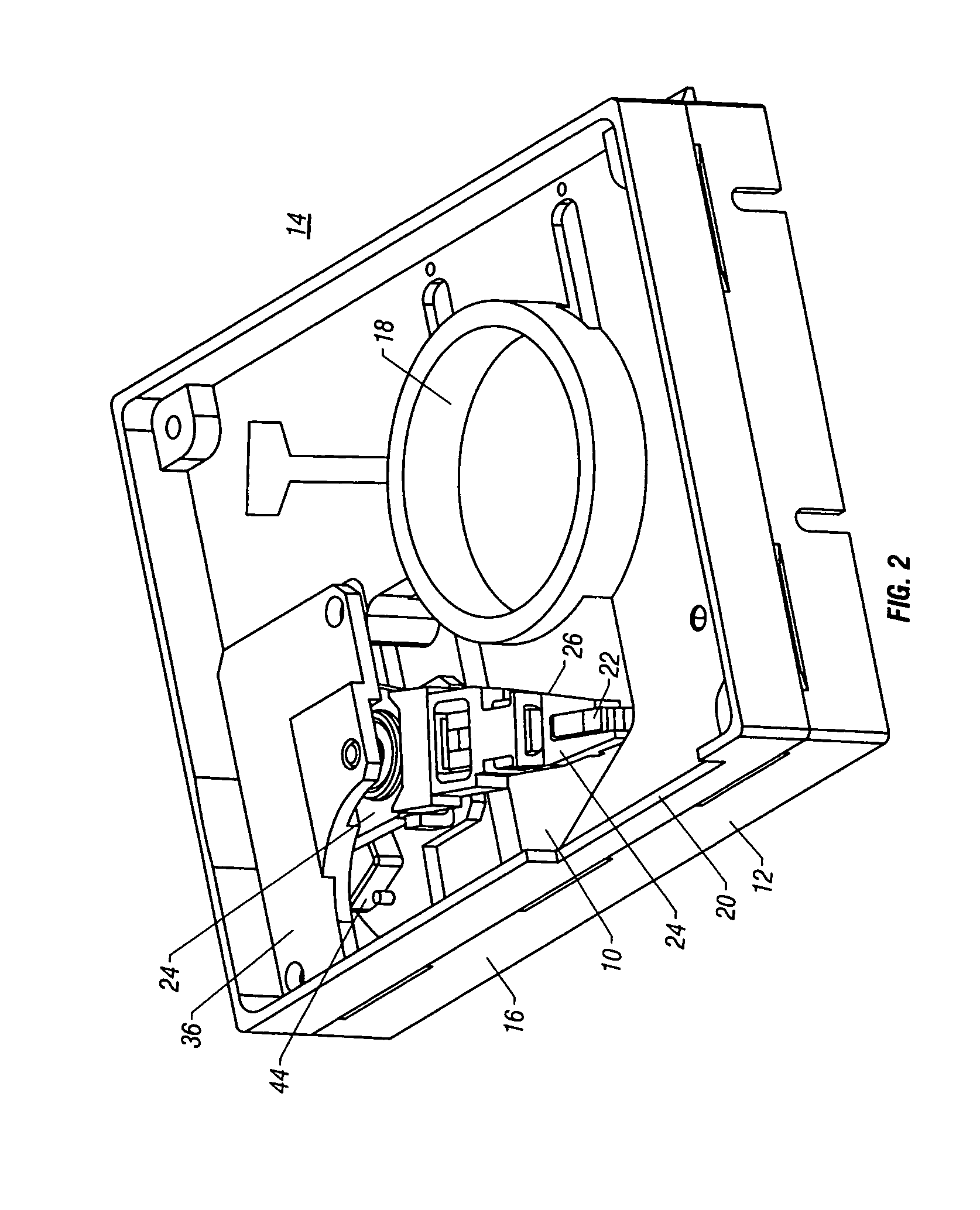
[0070]Turning to FIG. 2, the tilt focus mechanism 10 is shown within the housing 12 of an optical drive 14. The housing 12 includes a base plate 16 having an aperture 18 for receiving a spin motor (not shown) and a slot 20 to receive a diskette containing an optical disk (not shown). The cover plate has been removed. A diskette is inserted into the slot 20 and engages the spin motor positioned in aperture 18. An optical pick up unit 22 is positioned at the distal end of the tilt focus mechanism 10 and directs a light beam (not shown), such as a laser, to the optical disk which is spinning at a rapid rate.
[0071]The light beam may be used to write information to the disk or may be used to read information resident on the disk. Because information is stored on the disk in tracks, typically concentrically arranged, the optical pick up unit (OPU) 22 must be able to traverse the surface of the disk from the inside to the outside diameter in order to access the information formatted on the...
third embodiment
[0080]the present invention is shown in FIGS. 16-22. In general, this embodiment includes a tracking arm 100 for course movement in the X-Y direction (parallel to the surface of the optical disk) and a focus arm 102 for fine tracking and for focus movement in the Z direction (perpendicular to the disk surface). Thus, unlike the tracking arm 24 in the first two embodiments, tracking is accomplished by two stages rather than one. Like the tracking arm 24 in the first two embodiments, the tracking arm 100 includes a bearing mount bore 104 for receiving a bearing cartridge 106 which allows the tracking arm 100 to pivot about a shaft 108 mounted between a tracking VCM return plate and a VCM magnet plate (not shown) of the optical drive. As should be appreciated by one skilled in the art, as an alternative, the shaft 108, in this embodiment or in any of the disclosed embodiments, may be fixed or stationary. A coil 110, wound around bobbin 112, is mounted between a pair of support members ...
fourth embodiment
[0086]A fourth embodiment is disclosed in FIGS. 23-29. In general, this embodiment comprises a single actuator arm 200 having a bearing bore mount 202 which mounts to a bearing cartridge 204. The bearing cartridge 204 is rotatably connected to a shaft 206 mounted between a tracking VCM return plate 208 and the cover or a similar cap structure (not shown). For coarse and fine tracking purposes, the actuator arm 200 moves in a conventional manner responsive to torque induced by VCM 210. The VCM 210 comprises a coil 212 wound around a bobbin 214 placed within a pair of arms 216 and 218 at the rear end of the actuator arm 200. Permanent magnets 220 and 222, in cooperation with alternating current flowing in the coil 212 and the return path provided by tracking VCM return plate 208 and tracking VCM magnet plate 224, create the necessary torque to pivot the actuator 200 about the shaft 206. The tracking VCM magnet plate 224 further includes an aperture 226 to provide clearance for the sha...
PUM
 Abstract
Description
Claims
Application Information
 - R&D
- Intellectual Property
- Life Sciences
- Materials
- Tech Scout
- Unparalleled Data Quality
- Higher Quality Content
- 60% Fewer Hallucinations
Browse by: Latest US Patents, China's latest patents, Technical Efficacy Thesaurus, Application Domain, Technology Topic, Popular Technical Reports.
© 2025 PatSnap. All rights reserved.Legal|Privacy policy|Modern Slavery Act Transparency Statement|Sitemap|About US| Contact US: help@patsnap.com


