
System and method for real-time configurable monitoring and management of task performance systems

a task performance and task technology, applied in the field of system and method for real-time configurable monitoring and management of task performance systems, can solve the problems of complex industrial application design, prototyping, and implementation process, and achieve the effects of reducing the complexity of the system

Inactive Publication Date: 2008-02-12
PATHWAY TECH INC
View PDF8 Cites 19 Cited by
  • Summary
  • Abstract
  • Description
  • Claims
  • Application Information

AI Technical Summary

Benefits of technology

"The present invention is a system and method for creating and using an interactive visual instrument panel for monitoring and managing target systems in real-time. The instrument panel is designed based on the user's requirements and the attributes of the target system. The system uses a data handling system to ensure reliable transmission of real-time data from the target system. The invention provides an interactive GUI with novel tools and functionality for easy design and reconfiguration of the instrument panel. The system can be used with any form of visual design and modeling tools for rapid and inexpensive design, prototyping, re-design, scaling, modification, and testing of task performance systems. The invention allows for multiple display configurations for collective monitoring of one or more target systems by geographically dispersed users or configuration of specific instrument panels for benchmarking multiple variants of the same system at once."

Problems solved by technology

Traditionally, the process of design, prototyping, and implementation of complex industrial applications (such as manufacturing process control, multi-component devices and (such as manufacturing process control, multi-component devices and other systems or devices), has been an extremely difficult, costly and time consuming task.
Typically, this process involved a long iterative, and often empirical, process, of formulating the requirements of the desired system, conceptually planning the system, developing a prototype, writing programs or other code necessary for implementation, testing the implemented prototype and then repeating many of the steps, in most cases including the arduous and frustrating coding of new programs, even when minor changes to the prototype are necessary.
In cases of more serious issues, the entire system is often re-designed further consuming a great deal of time and resources.
This trial and error approach of system and device design has been a challenge for engineers and designers for years.
1) Design the desired target system functionality;
2) Break down the target system manually into distributed target components requiring slight modification in design, model each component and their connections separately to correspond to a real-world target device or system, and assign a portion of the desired functionality to each component, and establish connections between appropriate components;
3) Write appropriate software code to cause each component to perform their assigned functionality as well as to ensure proper communication and data interchange between various components
3) Simulate the operation of the system, testing and monitoring one component at a time; and
4) Manage the system (i.e., issue commands such as start, stop, record progress or status), one component at a time.
5) If problems occur, repeat one or more of the previous steps until the target system performs acceptably.
Because the key actions for all of the above tasks must be performed manually by the user, even with the assistance of the most powerful currently available design tools, the design-to-implementation cycle in continuous product development industries (such as automotive and aerospace industries), remains undesirably long.
In addition, changes to the system architecture or to system components during the prototyping process must be manually propagated through the entire system, thus resulting in a further significant delay and expense.
Furthermore, the most frustrating and difficult tasks for the user of previously known system design software tools—the second and third steps shown above—are still an ever-present requirement.
While the above-incorporated novel IRMM system has numerous advantages over all previously know approaches, it does not in itself provide a solution to one of the greatest challenges facing not only the developers of task performance systems and devices, but also those who operate, maintain, troubleshoot and work with existing complex task performance systems—the ability to control and monitor (locally and / or remotely) the operation of an entire remote task performance system (whether a system in development or an existing working system) or a device, remotely in real time without any loss of system-related information by the monitoring / managing user.
The secondary challenge of providing an easy to use customizable interface for simultaneously monitoring and managing various aspects of a remote system during its operation has likewise gone substantially unanswered.
However, the Austin system provides that capability only for viewing the live feed for one component of the remote system at a time.
Most other approaches suffer from similar limitations.
Furthermore, the majority of existing system design and development tools are generally limited to utilization in the field of embedded system or industrial process control design and thus even their limited “one-at-a-time” remote monitoring / management features cannot be readily used for monitoring in other forms of task performance systems or devices.
In addition, most previously known monitoring / management solutions are concerned with the user working with a single task performance system, with only complex, expensive and proprietary tools being capable of simultaneously working with many systems.
Yet another problem faced by previously know systems is that certain task performance systems have limited capacity to continuously record data without interruption, and require significant modification or enhancement to enable even short term real-time data collection.
Finally, the design of graphical user interfaces for system monitoring and control using currently available tools is still a relatively arduous process, not as much in terms of designing the graphical portions of GUIs, but in building GUIs to monitor / manage specific systems.
This may be problematic in system development applications where monitoring / management requirements can change quickly, necessitating constant time-consuming GUI re-design.

Method used


Image

  • System and method for real-time configurable monitoring and management of task performance systems
  • System and method for real-time configurable monitoring and management of task performance systems
  • System and method for real-time configurable monitoring and management of task performance systems

Examples


first embodiment

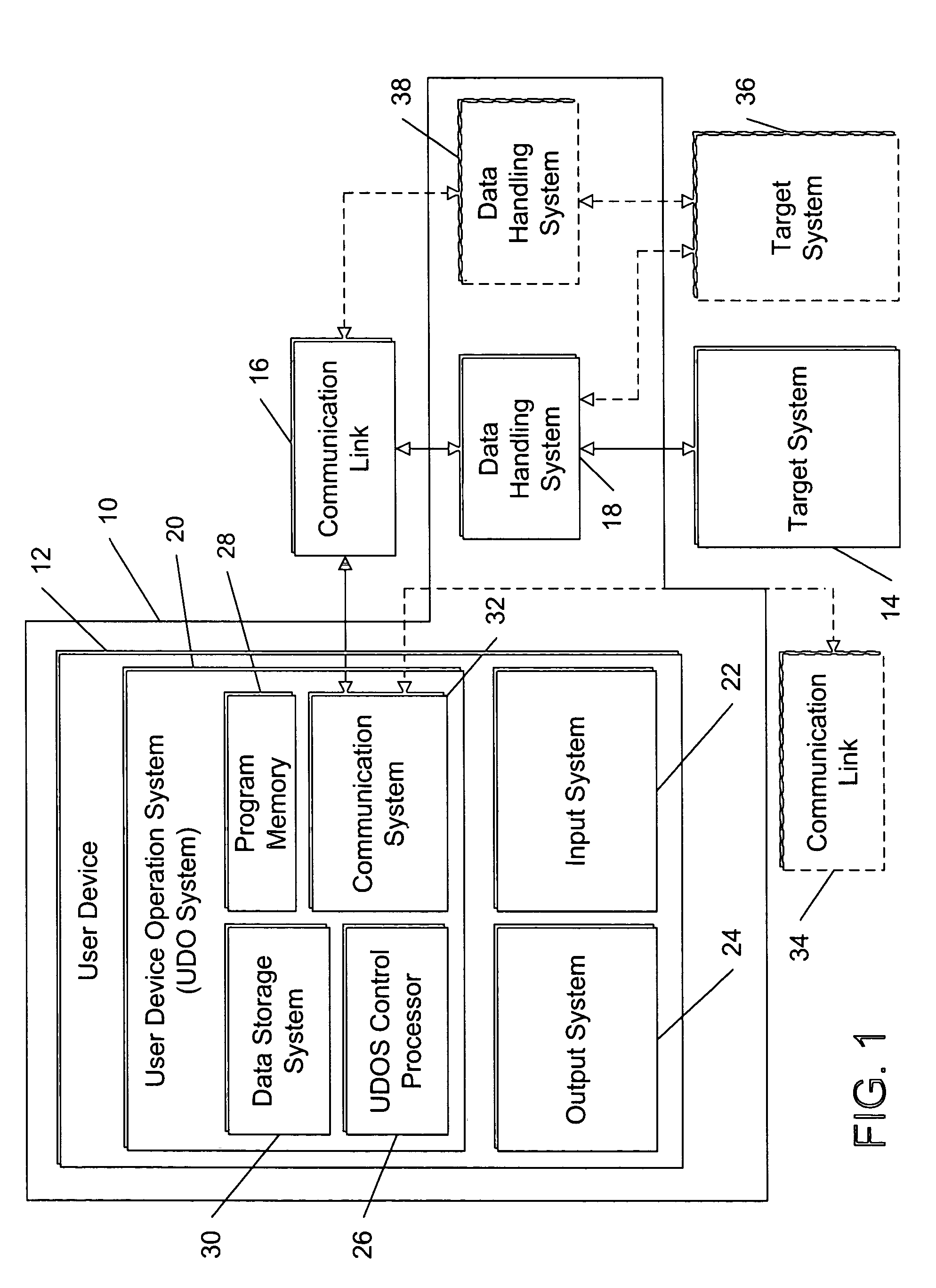
[0046]Referring now to FIG. 1, the inventive IRMM system 10 is shown. The key novel features of the IRMM system 10 are embodied in the inventive processes, described in greater detail below in connection with FIGS. 6-14, that may be implemented in whole or in part as one or more executable programs, embedded functions, or other form of data processing tasks by one or more components thereof. These inventive processes enable the user to fully utilize the previously summarized novel and advantageous features of the IRMM system 10, as well as take advantage of numerous other novel features and options described below in connection with various figures.

[0047]The IRMM system 10 includes a user device 12 for enabling the user to build and / or use an interactive visual instrument panel for monitoring and / or managing one or more target systems, with the instrument panel being configured based on the user-defined requirements and based on the attributes of the target system(s) being monitored...

second embodiment

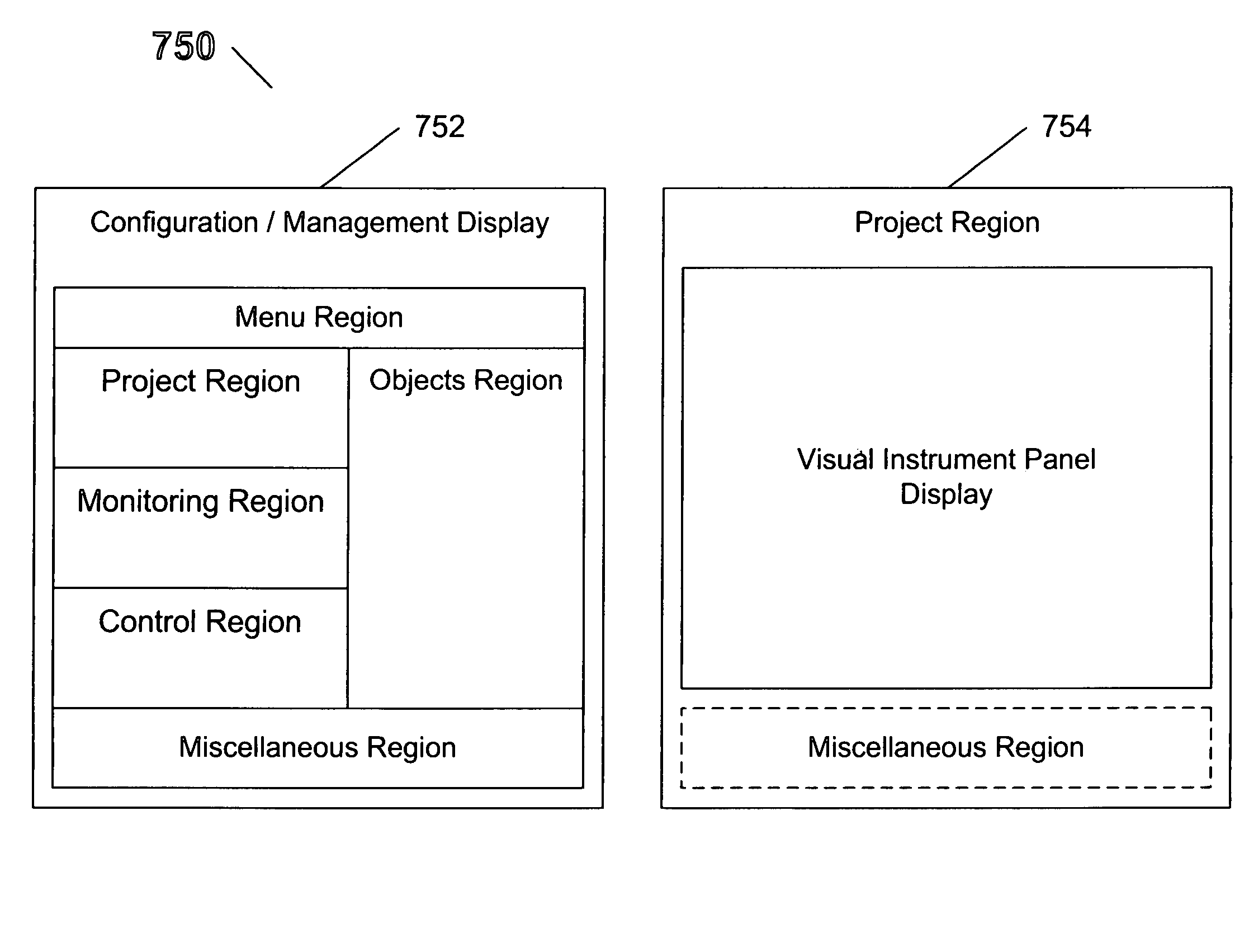
[0104]Referring now to FIG. 22, a graphical representation of an exemplary GUI that may be displayed to the user by the user device 12 via the output system 24 (such as a video monitor), and utilized by the user via the input system 22 to interact with the process 400 (and its sub-processes), is shown as an interface 700. It should be noted that the interface 700 only shows the specific front-end elements relevant to the process 400. Furthermore, the exact sizes and positioning of the various interface 700 regions is shown by way of example only—the regions may be readily re-seized and re-positioned as a matter of design choice without departing from the spirit of the invention.

[0105]The interface 700 includes a menu region 702 which may contain selectable menu items to interact with or otherwise control operations of the process 400 and other processes that may be performed by the user device 12, a monitoring element region 704 that displays all VI_ELEMENTs related to MINF attribut...


PUM


Abstract

The system and method of the present invention enable the user to build and / or use an interactive visual instrument panel for monitoring and / or managing one or more target systems locally or remotely in real-time, with the instrument panel being configured based on the user-defined requirements and based on the attributes of the target system(s) being monitored and / or managed. In one embodiment of the present invention a novel data handling system is provided for ensuring that the target system is able to continuously transmit real-time data without any data loss and without interrupting its operation.

Description

CROSS REFERENCE TO RELATED APPLICATIONS[0001]The present patent application is a continuation-in-part (CIP) of the commonly assigned U.S. patent application Ser. No. 10 / 911,161, entitled: “SYSTEM AND METHOD FOR RAPID DESIGN, PROTOTYPING, AND IMPLEMENTATION OF DISTRIBUTED SCALABLE ARCHITECTURE FOR TASK CONTROL AND AUTOMATION”, filed Aug. 2, 2004, which in turns claims priority from the U.S. Provisional Patent provisional patent application Ser. No. 60 / 492,771 entitled “SYSTEM AND METHOD FOR RAPID DESIGN, PROTOTYPING AND IMPLEMENTATION OF DISTRIBUTED SCALABLE ARCHITECTURE FOR TASK CONTROL AND AUTOMATION” filed Aug. 2, 2003.FIELD OF THE INVENTION[0002]The present invention relates generally to a data processing system and method for enabling real-time access to and control of operations of a task performance system or device, and more particularly for an interactive user-configurable scalable data processing system with a user-customizable interface for real-time remote monitoring and ...

Claims


Application Information

Patent Timeline
Patent Type & Authority Patents(United States)
IPC IPC(8): G06F3/00G06F9/44G06F17/50G06Q10/00
CPCG05B15/02G05B23/0267G06F8/38G06F11/328G06F17/5009G06Q10/00G06F30/20
Inventor ANANTH, VISWANATHSURIANARAYANAN, ANANTHAKRISHNAN
Owner PATHWAY TECH INC
Learn More