
Exposure apparatus, exposure method and semiconductor device production method

a technology of exposure apparatus and exposure method, which is applied in the field of exposure apparatus, exposure method and exposure method of semiconductor device production method, can solve the problems of increasing the time required for temperature to restitute, and increasing the temperature of the mask. , to achieve the effect of high accuracy, increasing the mask temperature, and increasing the mask temperatur

Inactive Publication Date: 2008-02-05
SONY CORP
View PDF17 Cites 0 Cited by
  • Summary
  • Abstract
  • Description
  • Claims
  • Application Information

AI Technical Summary

Benefits of technology

[0015]The present invention is performed in consideration of the above circumstances, an object of the present invention is to produce an exposure apparatus and an exposure method that rise in temperature of the mask by irradiating a charged particle beam can be controlled, displacement of the pattern position associated with rise in temperature of the mask can be prevented and the pattern can be projected on an exposed object with a high accuracy.
[0016]The other object of the present invention is to produce a semiconductor device production method that rise in temperature of the mask by irradiating a charged particle beam can be controlled and displacement of the pattern position associated with rise in temperature of the mask can be prevented, the pattern can be projected on an exposed object with a high accuracy and a circuit pattern can be formed with a high accuracy.
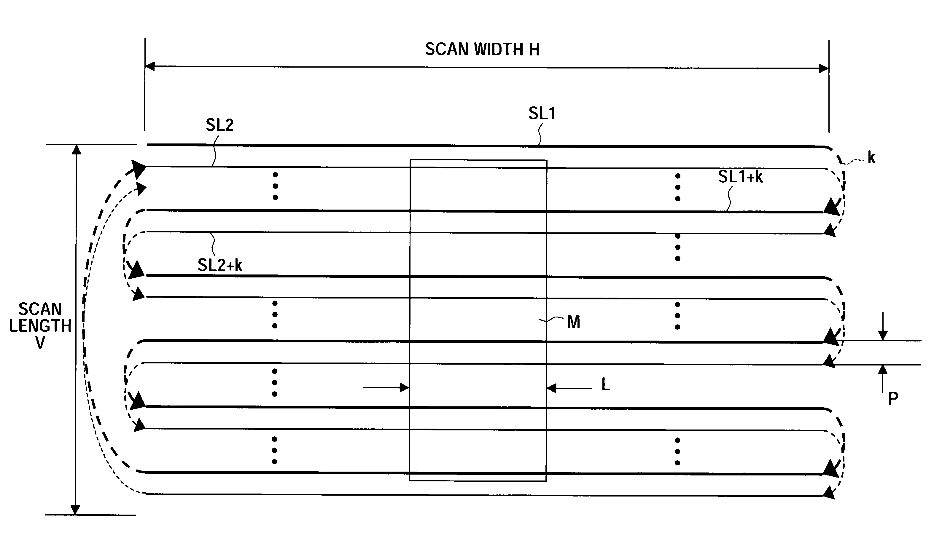
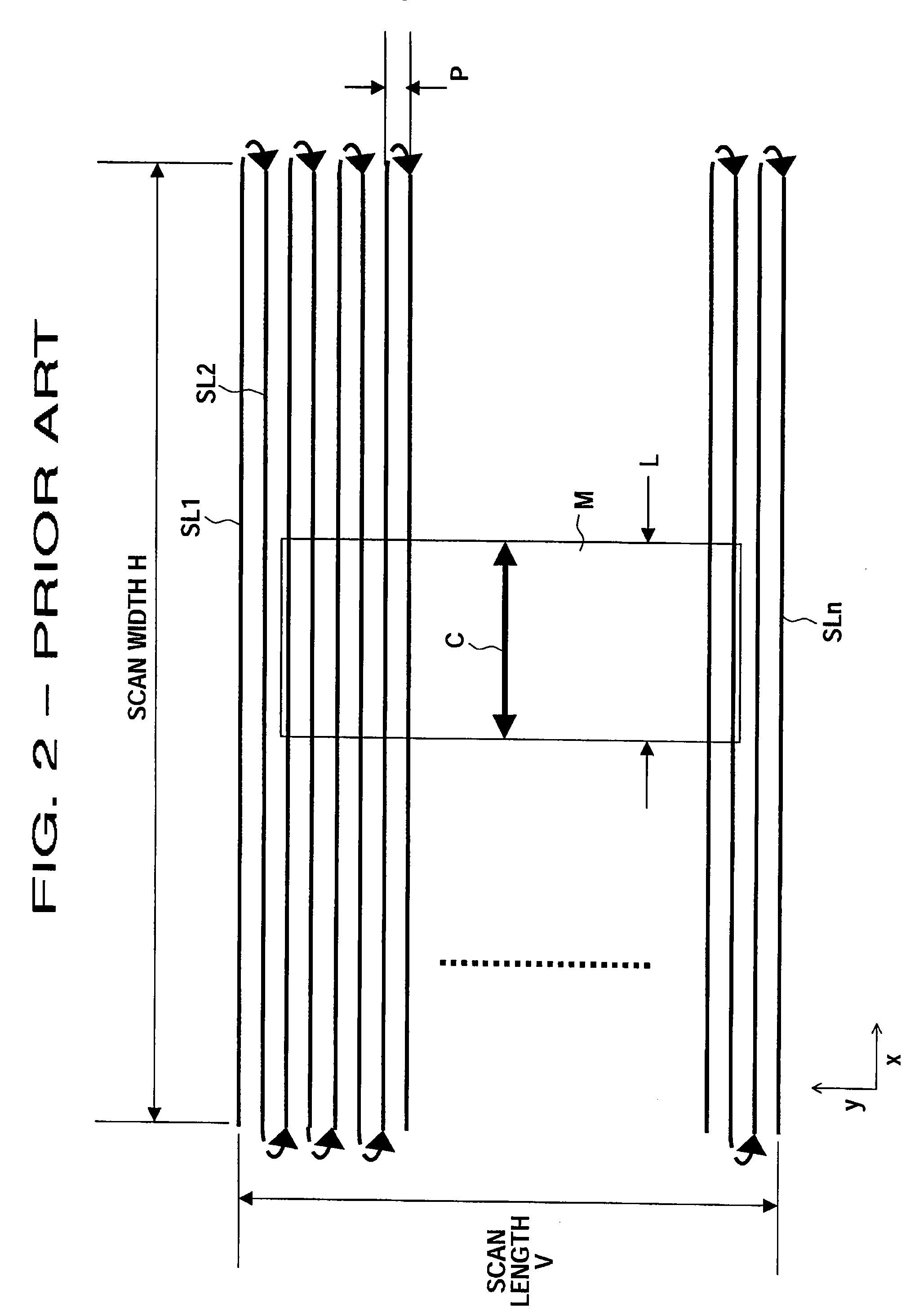
[0017]To accomplish the above object, an exposure apparatus of the present invention has a mask having a pattern to be projected on an exposed object, a scan line set means setting a plurality of scan lines to be scanned by a charged particle beam on the mask, and a charged particle beam scan means that all the scan lines are scanned by the charged particle beam by performing interlaced-scanning by number of overjumped lines that can control rise in temperature of the mask due to overlapping of the charged particle beams, and for repeating the interlaced-scanning for the overjumped scan lines to scan all the scan line.

Problems solved by technology

However, if the membrane is sectioned by a plurality of beams, since an aperture of the pattern cannot be formed at the position of the beams, for example like a mask structure described in the Japanese unexamined patent publication No. 2003-59819, there is a problem that four mask regions of the same size as the die is needed, and the scanning range of the electron beam becomes large.
Moreover, if the membrane is sectioned small by the beams, the problem that complementary division of the pattern becomes complicated arises.
However, if size of one membrane forming an aperture of the pattern becomes large, an important issue such as rise in temperature because of the following reason in exposing and generation of displacement of the pattern position over an acceptable value associated with this occurred.
Therefore, if size of the membrane becomes too large, time required for temperature to restitute becomes longer.
As mentioned above, in the case that size of the membrane is made to be large, an important issue such as rise in temperature of the membrane and displacement of the pattern position associated with that occurred.
If the pattern position is displaced, error arises in the project pattern projected to the wafer arises and the pattern cannot be projected with a high accuracy.

Method used


Image

  • Exposure apparatus, exposure method and semiconductor device production method
  • Exposure apparatus, exposure method and semiconductor device production method
  • Exposure apparatus, exposure method and semiconductor device production method

Examples


Embodiment Construction

[0047]Preferred embodiments of the present invention will be described with reference to the accompanying drawings.

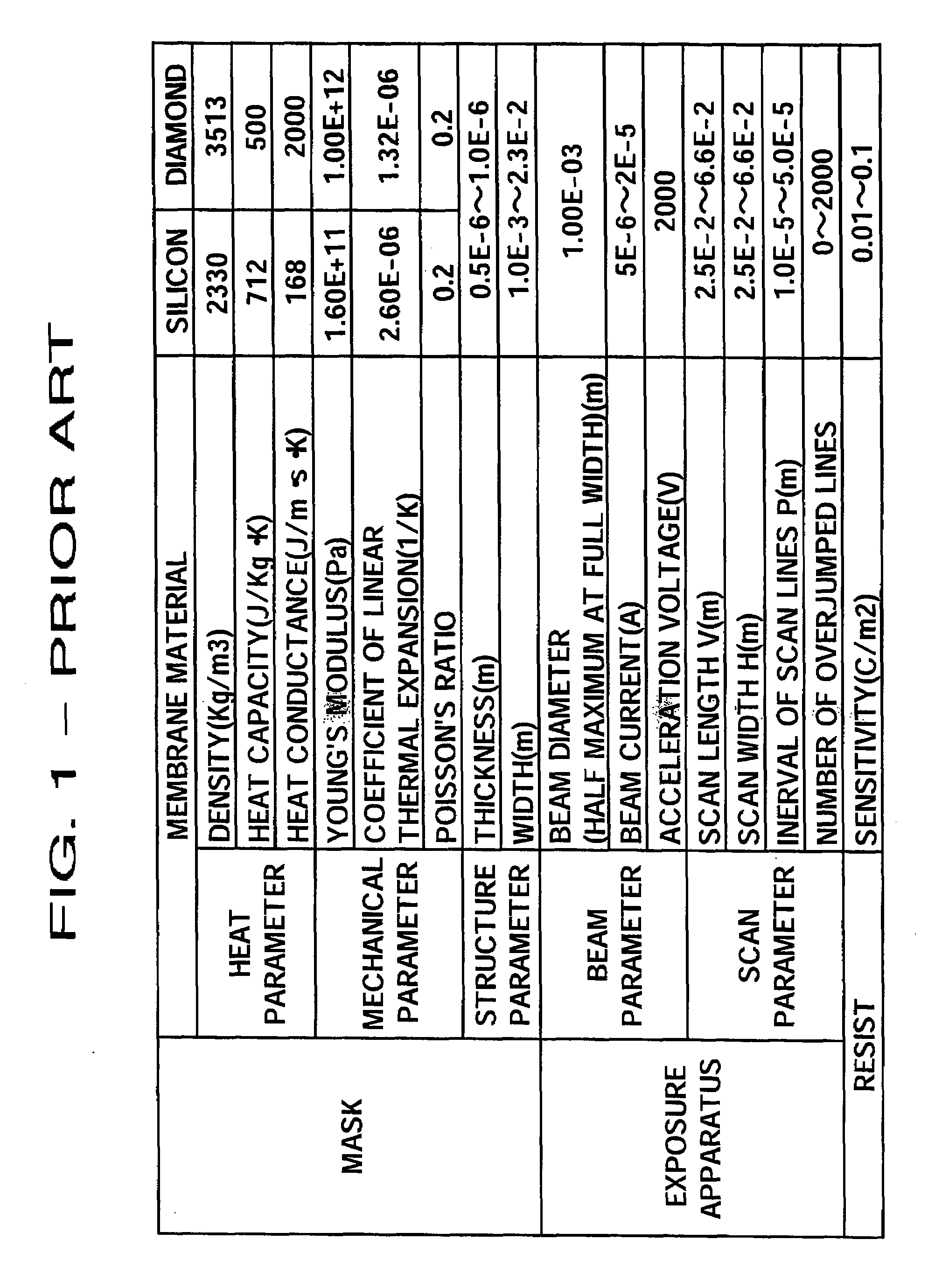
[0048]FIG. 1 shows an example of a property value of an exposure apparatus concerning the present embodiment, a mask used in the exposure apparatus and a resist exposed by the mask.

[0049]As shown in FIG. 1, for considering heat displacement of a pattern by thermal expansion of the mask, it is necessary to clarify heat parameters, such as density, heat capacity and heat conductance, mechanical parameters, such as Young's modulus, coefficient of linear thermal expansion and Poisson's ratio, and structure parameters, such as thickness and width. Consequently, as an example, the above parameters of silicon and diamond that are leading materials for the membrane now are shown in FIG. 1. The material is not limited in the present invention, further preferable material can be used, however the case of adopting silicon and diamond is explained for an example in the present embo...


PUM

PropertyMeasurementUnit
thicknessaaaaaaaaaa
thicknessaaaaaaaaaa
sizeaaaaaaaaaa

Abstract

An exposure method and a semiconductor device production method that control a rise in temperature of a mask irradiated by a charged particle beam. A displacement of the position of a pattern accompanying with the rise in temperature of the mask and the pattern are projected on an exposed object with a high accuracy. After an electron beam scans one scan line, scan lines are jumped by over a number of scan lines and the electron beam scans the next scan line. Since the number of the overjumped lines is a set number that control the temperature rise of a membrane by overlapping of the electron beam, the temperature rise is controlled by an interlaced-scanning. After one interlaced-scanning, similar to the above the scan lines are jumped over by the predetermined number of scan lines and the electron beam scans the next scan lines.

Description

BACKGROUND OF THE INVENTION[0001]1. Field of the Invention[0002]The present invention relates to, for example, an exposure apparatus that scans a mask by a charged particle beam to project a pattern, an exposure method, and a semiconductor device production method forming a circuit pattern of the semiconductor device by using the exposure method.[0003]2. Description of the Related Art[0004]A proximity exposure technology of equal scale that a mask called as a stencil mask that a mask pattern is formed by an aperture is located close to a wafer and a low acceleration electron beam is irradiated to the mask to perform an exposure is disclosed (refer to Japanese examined patent publication No. 2951947). For realizing this exposure technology, the development of a stencil mask with a thin film, which is called as membrane, having a thickness from about 500 nm to 1 μm and the development of resist process of 100 nm or less are performed now.[0005]For keeping mechanical strength of the me...

Claims


Application Information

Patent Timeline
Patent Type & Authority Patents(United States)
IPC IPC(8): G21G5/00G03F7/20H01J37/147H01J37/305H01J37/317H01L21/027
CPCB82Y10/00B82Y40/00H01J37/3174G03F7/2047H01J2237/31794G03F7/70375
Inventor MORIYA, SHIGERU
Owner SONY CORP
Learn More