
Hot plate with stainless steel top

a technology of stainless steel and hot plate, applied in the field of hot plate, can solve the problems of glass breaking, corrosion and/or oxidation of copper, iron and aluminum, and may not be commercially practical for less expensive hot plate, and achieve the effects of reducing the tendency of a vessel being heated to move, reducing buckling and crowning, and efficient heating cycl

Inactive Publication Date: 2008-02-05
THERMO FISHER SCI ASHEVILLE
View PDF13 Cites 10 Cited by
  • Summary
  • Abstract
  • Description
  • Claims
  • Application Information

AI Technical Summary

Benefits of technology

"The present invention provides a stainless steel hot plate for heating substances in industrial and laboratory processes. The hot plate has a stainless steel top plate that is resistant to corrosion and maintains an efficient heating cycle over a full range of operation. The hot plate minimizes buckling and crowning when heated and reduces the tendency for the vessel being heated to move on the hot plate. The hot plate is especially useful in a laboratory environment. The invention also includes a heating unit, a base unit, and a compression plate for securing the stainless steel top plate to the base unit. The stainless steel top plate has an upper surface with a centrally located depression and a concavity to minimize crowning when heated. The invention provides a long service life and efficient heating cycle for industrial and laboratory processes."

Problems solved by technology

It is known to make hot plate tops from various materials, for example, copper iron, glass, aluminum and stainless steel; but all of those materials have disadvantages.
For example, glass is breakable; and copper, iron and aluminum are subject to corrosion and / or oxidation from exposure to chemicals that may be present in the laboratory.
Corrosion may be reduced by coating those materials, but such coatings are expensive and may not be commercially practical for less expensive hot plates.
Stainless steel has an advantage of being resistant to corrosion, but it has a disadvantage of being a relatively poor thermal conductor.
Thus, the varying temperatures and resulting varying thermal expansions produce a convex-shaped top surface, which reduces an area of contact between the top surface and the vessel being heated and substantially reduces the efficiency of the heating process.
Further, the crowned or convex shaped top surface is more susceptible to the vessel moving or walking over the top surface in the presence of a vibration.

Method used


Image

  • Hot plate with stainless steel top
  • Hot plate with stainless steel top
  • Hot plate with stainless steel top

Examples


Embodiment Construction

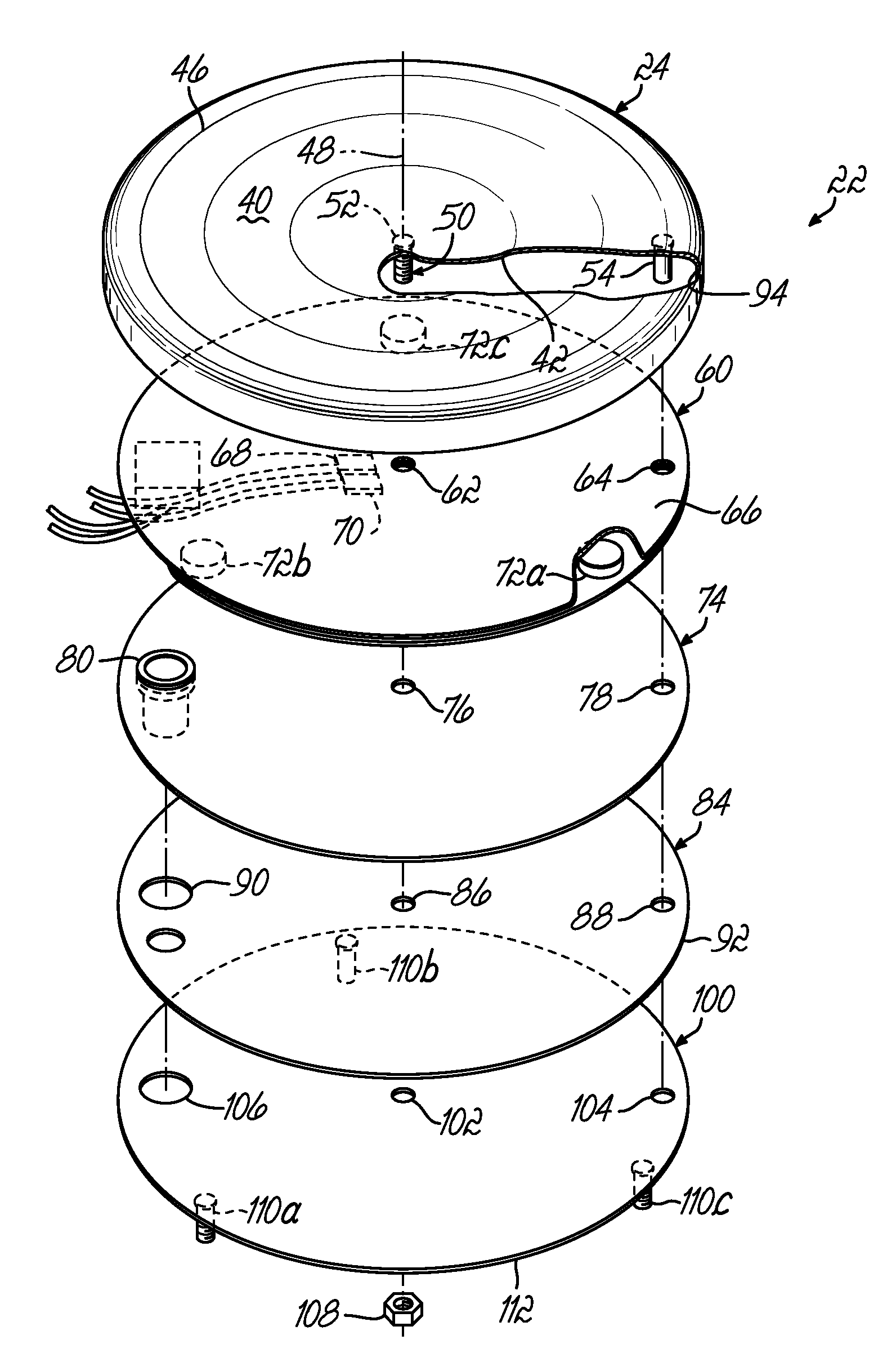
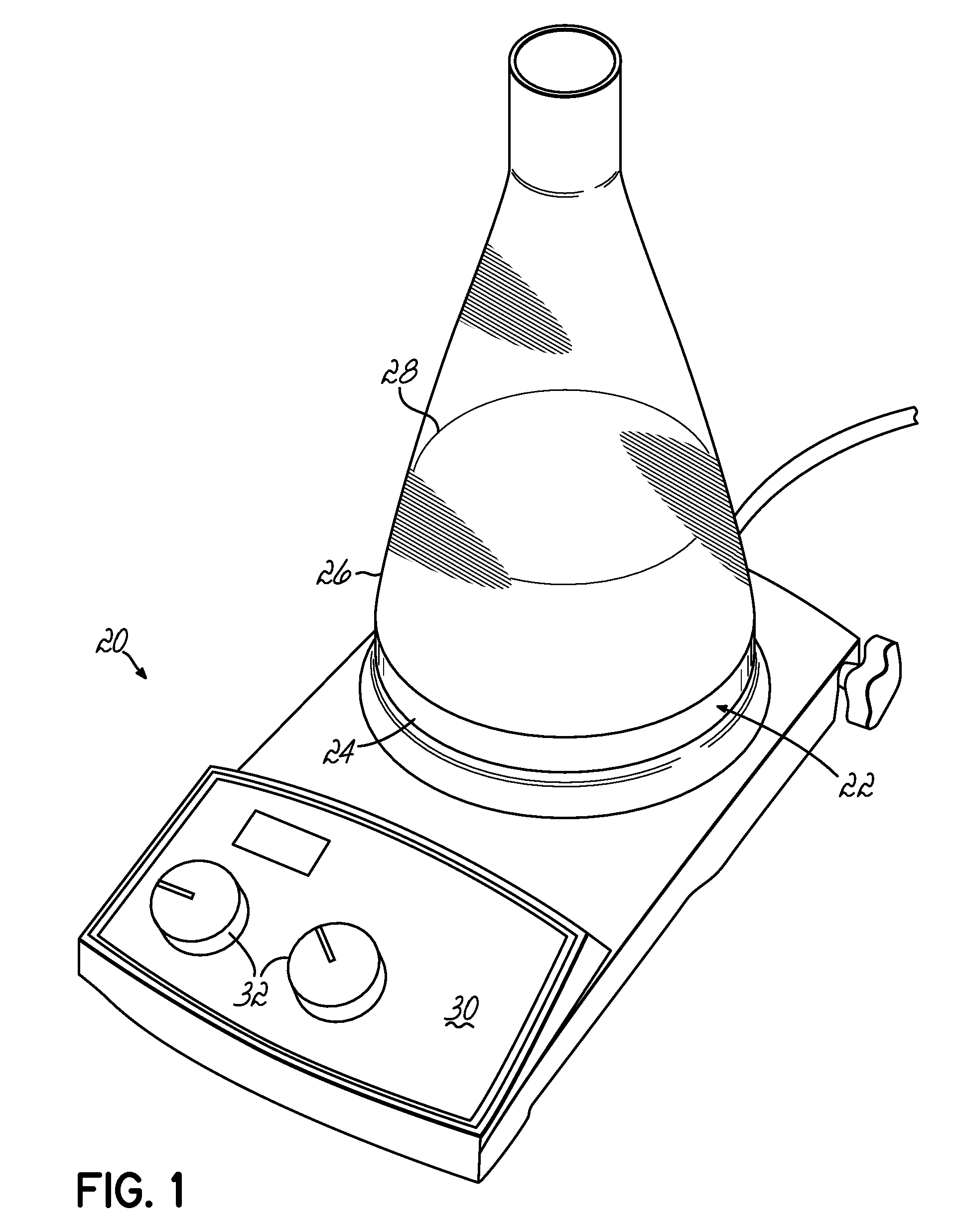
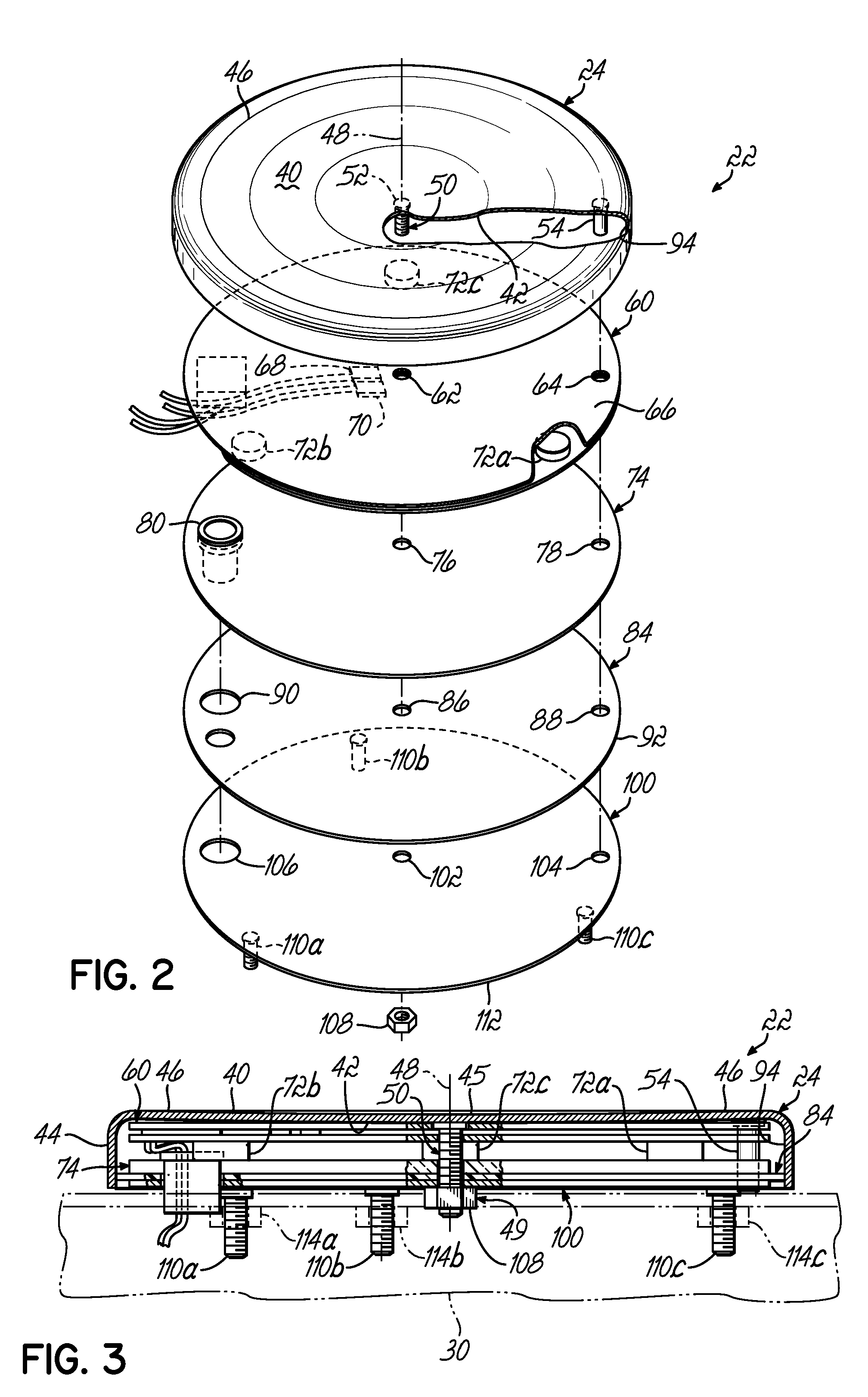
[0018]Referring to FIG. 1, a stirring hot plate 20 includes a heating plate assembly or unit 22 having a stainless steel top plate 24 for supporting a vessel 26 containing a substance 28 to be heated and / or stirred. The heating plate unit 22 is supported by a base unit 30, and often, the base unit 30 provides three points of support for the heating plate unit 22. The base unit 30 provides user operable I / O (input / output) devices 32 that, in a known manner, provide input data and commands to analog or digital controls (not shown) inside the base unit 30, which are operable to control an electric heating element. The base unit 30 may also, in a known manner, house a magnetic stirring device and associated user I / O devices, which are operable to provide a rotating magnetic field above the top plate unit 22, thereby rotating a magnetic stirring rod inside the vessel 26.

[0019]Referring to FIG. 2, the top plate 24 of the heating top plate assembly 22 is made of a stainless steel material,...


PUM

PropertyMeasurementUnit
depthaaaaaaaaaa
thickaaaaaaaaaa
displacementaaaaaaaaaa

Abstract

A hotplate with a stainless steel top plate to support a vessel. The stainless steel top plate has an upper surface with a substantially centrally located depression having a depth and area generally sufficient to absorb upward crowning of the top plate when heated. A heating unit is in a heat transfer relation with the stainless steel top plate, and a base unit is connected to the heating plate assembly; however, the base unit is not fastened directly to the stainless steel top plate, so that the stainless steel top plate can expand more uniformly when heated.

Description

FIELD OF THE INVENTION[0001]This invention relates generally to hot plates and more particularly, to heating surfaces for a hot plate to heat substances in a vessel or container placed on the hot plate.BACKGROUND OF THE INVENTION[0002]Hot plates are devices that provide a heated horizontal surface and are widely used in a variety of industrial and laboratory settings for heating substances contained in vessels. For instance, hot plates are commonly used for heating chemicals and other materials in open or closed vessels, in order to promote a chemical reaction or change in properties of the materials. A typical hot plate includes a heating element disposed below or embedded within a horizontal support surface for the vessel to be heated. A housing or base unit is usually provided for containing the electrical leads and connections between the heating element and an electrical supply line, as well as other components such as switches, over-temperature shut-off devices, potentiometer ...

Claims


Application Information

Patent Timeline
Patent Type & Authority Patents(United States)
IPC IPC(8): H05B3/68H05B3/06
CPCB01L7/00H05B3/68H05B3/72B01L3/08B01L2300/1827
Inventor LOCKWOOD, MARK D.RINIKER, PETEREDWARDS, JAMES R.
Owner THERMO FISHER SCI ASHEVILLE
Learn More