
Self-propelling crusher

a self-propelled, crushing machine technology, applied in the direction of agriculture tools and machines, grain treatment, manufacturing tools, etc., can solve the problems of reducing the productivity of crushed products and the crushing efficiency of the crushing devi

Inactive Publication Date: 2008-01-15
NIHON KENKI CO LTD
View PDF7 Cites 11 Cited by
  • Summary
  • Abstract
  • Description
  • Claims
  • Application Information

AI Technical Summary

Benefits of technology

[0006]In view of the above-mentioned problems in the state of the art, an object of the present invention is to provide a self-propelled crushing machine capable of preventing a reduction of crushing efficiency even when a heavy load is imposed on a crushing device.
[0007](1) To achieve the above object, the present invention provides a self-propelled crushing machine for crushing target materials to be crushed, wherein the machine comprises a crushing device; a hydraulic drive system including a crushing device hydraulic motor for driving the crushing device, at least one hydraulic pump for driving the crushing device hydraulic motor, and a prime mover for driving the hydraulic pump; crushing device load detecting means for detecting a load condition of the crushing device; and control means for executing control to increase a revolution speed of the prime mover in accordance with a detected signal from the crushing device load detecting means.
[0008]With the present invention, when a heavy load is imposed on the crushing device and the load pressure of the crushing device hydraulic motor is increased during the crushing work due to, e.g., excessive supply of the target materials (materials to be crushed), the crushing device load detecting means detects such an overload condition, and the control means increases the revolution speed of the prime mover, thereby increasing the horsepower of the prime mover. In other words, as compared with the known structure having a possibility that the rotational speed of the crushing device hydraulic motor lowers and productivity of crushed products reduces in the overload condition where the load pressure of the crushing device hydraulic motor is increased and the engine revolution speed lowers, the present invention is able to prevent a reduction of the crushing efficiency, which is caused by a lowering of the rotational speed of the crushing device hydraulic motor, by increasing the horsepower of the prime mover in the overload condition of the crushing device as described above.
[0010]With the present invention, the so-called total horsepower control is performed such that the delivery rates of the first hydraulic pump and the second hydraulic pump are controlled depending on the delivery pressure of the first hydraulic pump for supplying a hydraulic fluid to the crushing device hydraulic motor and on the delivery pressure of the second hydraulic pump for supplying a hydraulic fluid to the auxiliary hydraulic actuator, and that a total of the torques of the first hydraulic pump and the second hydraulic pump is controlled to be held smaller than the horsepower of the prime mover. As a result, the horsepower of the prime mover is effectively distributed to the first and second hydraulic pumps depending on the difference between their loads, and hence the horsepower of the prime mover can be effectively utilized.

Problems solved by technology

This has resulted in problems that crushing efficiency of the crushing device reduces and productivity of crushed products lowers.

Method used


Image

  • Self-propelling crusher
  • Self-propelling crusher
  • Self-propelling crusher

Examples


Embodiment Construction

[0037]One embodiment of a self-propelled crushing machine of the present invention will be described below with reference to the drawings.

[0038]First, one embodiment of the self-propelled crushing machine of the present invention will be described with reference to FIGS. 1 to 16.

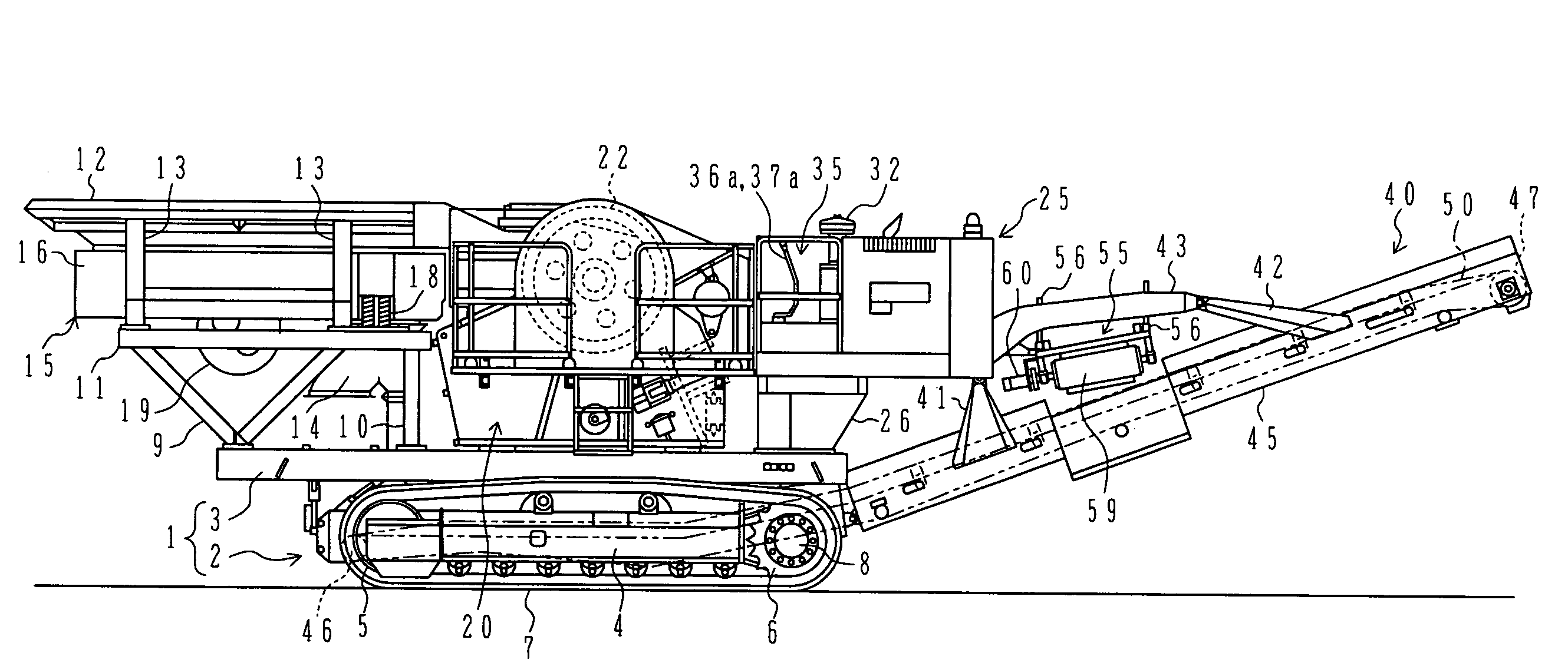
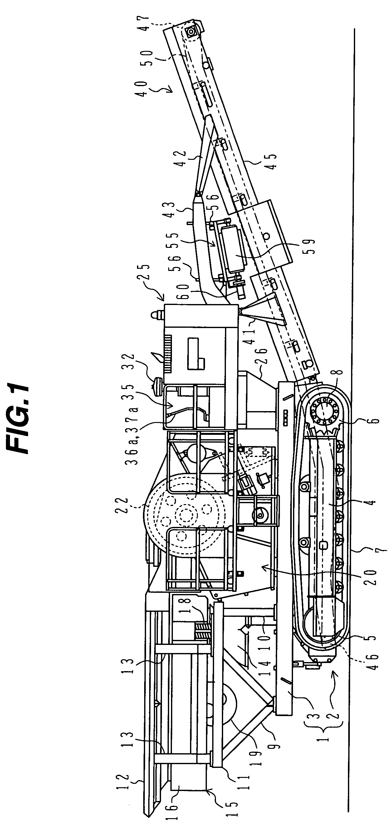
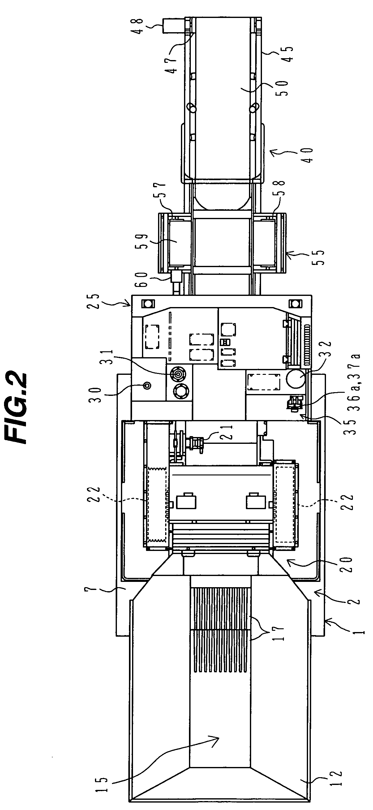
[0039]FIG. 1 is a side view showing an overall structure of one embodiment of the self-propelled crushing machine of the present invention, FIG. 2 is a plan view thereof, and FIG. 3 is a front view looking from the left side in FIG. 1.

[0040]In FIGS. 1 to 3, numeral 1 denotes a travel body. The travel body 1 comprises a travel structure 2 and a body frame 3 substantially horizontally extending on the travel structure 2. Numeral 4 denotes a track frame of the travel structure 2. The track frame 4 is connected to the underside of the body frame 3. Numerals 5, 6 denote respectively a driven wheel (idler) and a drive wheel which are disposed at opposite ends of the track frame 4, and 7 denotes a crawler belt (cat...


PUM


Abstract

A self-propelled crushing machine comprises a crushing device 20; a hydraulic drive system including a crushing device hydraulic motor 21 for driving the crushing device 20, a first hydraulic pump 62 for driving the crushing device hydraulic motor 21, and an engine 61 for driving the first hydraulic pump 62; a pressure sensor 151 for detecting a load condition of the crushing device 20; and a controller 84″ for executing control to increase a revolution speed of the engine 61 in accordance with a detected signal from the pressure sensor 151. Accordingly, even when a heavy load is imposed on the crushing device, a reduction of crushing efficiency can be prevented.

Description

TECHNICAL FIELD[0001]The present invention relates to a self-propelled crushing machine equipped with a crushing device for crushing target materials to be crushed, such as a jaw crusher, a roll crusher, a shredder, and a wood chipper.BACKGROUND ART[0002]Usually, crushing machines are employed to crush target materials to be crushed, e.g., rocks and construction wastes of various sizes generated in construction sites, into a predetermined size for the purposes of reuse of the wastes, smoother progress of work, a cost reduction, etc.[0003]As one example of those crushing machines, a mobile crusher generally comprises a travel body having left and right crawler belts, a crushing device for crushing target materials loaded through a hopper into a predetermined size, a feeder for guiding the target materials loaded through the hopper to the crushing device, a discharge conveyor for carrying the materials having been crushed into small fragments by the crushing device to the outside of t...

Claims


Application Information

Patent Timeline
Patent Type & Authority Patents(United States)
IPC IPC(8): B27C9/00B02C21/02B02C23/00B02C25/00
CPCB02C21/026B02C25/00B02C21/02
Inventor TANAKA, MASAMICHISHIBA, YOSHIMISHIOHATA, TADASHIHASHIMOTO, KENTARO
Owner NIHON KENKI CO LTD
Learn More