
Rolling method and rolling apparatus for flat-rolled metal materials

a technology of metal materials and rolling methods, which is applied in the direction of manufacturing tools, measuring devices, profile control devices, etc., can solve the problems of extremely low accuracy of the method of estimating the camber from the left-right difference of the rolling load, and difficulty in conducting camber control from the distal end of the rolled material,

Active Publication Date: 2007-12-25
NIPPON STEEL CORP
View PDF24 Cites 23 Cited by
  • Summary
  • Abstract
  • Description
  • Claims
  • Application Information

AI Technical Summary

Benefits of technology

This approach enables the stable production of flat-rolled metal materials with minimal or no camber, improving control accuracy and reducing the occurrence of camber-related defects, even as the rolls wear over multiple passes.

Problems solved by technology

The edger roll on the exit side must be saved back at the time of passing of the distal end of the rolled material in order to avoid impingement, and it is difficult, too, to conduct camber control from the distal end of the rolled material.
According to the invention relating to the camber control technology based on the rolling load left-right difference described in Japanese Unexamined Patent Publication (Kokai) No. 2001-105013, the method of estimating the camber from the left-right difference of the rolling load has extremely low accuracy and is not practical when the sheet thickness of the rolled material on the entry side is not uniform in the sheet width direction or when the temperature distribution of the rolled material is not uniform in the sheet width direction.
After all, it can be concluded that the problems of the prior art technologies described above result from the absence of the method that can measure and control very accurately and without a time delay the camber that occurs owing to various causes.

Method used


Image

  • Rolling method and rolling apparatus for flat-rolled metal materials
  • Rolling method and rolling apparatus for flat-rolled metal materials
  • Rolling method and rolling apparatus for flat-rolled metal materials

Examples


example

[0076]An example where the sheet rolling method of the invention described in (2) is executed by using the rolling mill shown in FIG. 8 will be explained. Learning of the control target value of the rolling direction force left-right difference that is based on the output of the camber measurement device 30 provided to the back of the rolling mill is executed while the learning gain is set to γ 0.3 and the control target value in the initial stage is set to zero. Incidentally, a constant within the range of 0.5 to 20 tonf / (mm / m) is set for each rolling condition and each rolling material as a constant α representing the gradient of the relation line between the rolling direction force left-right difference and the camber quantity.

[0077]Table 1 tabulates the control target values of the rolling direction left-right difference with respect to the typical number of rolling passes and the actual measurement value of the camber. As can be understood from Table 1, the camber actual measur...


PUM

PropertyMeasurementUnit
forceaaaaaaaaaa
rolling direction forceaaaaaaaaaa
camberaaaaaaaaaa

Abstract

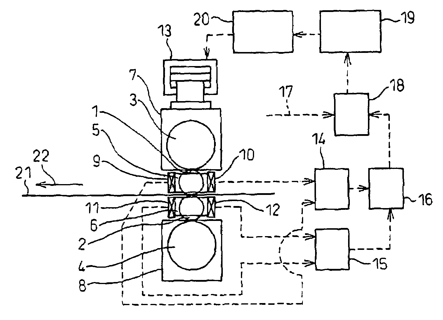
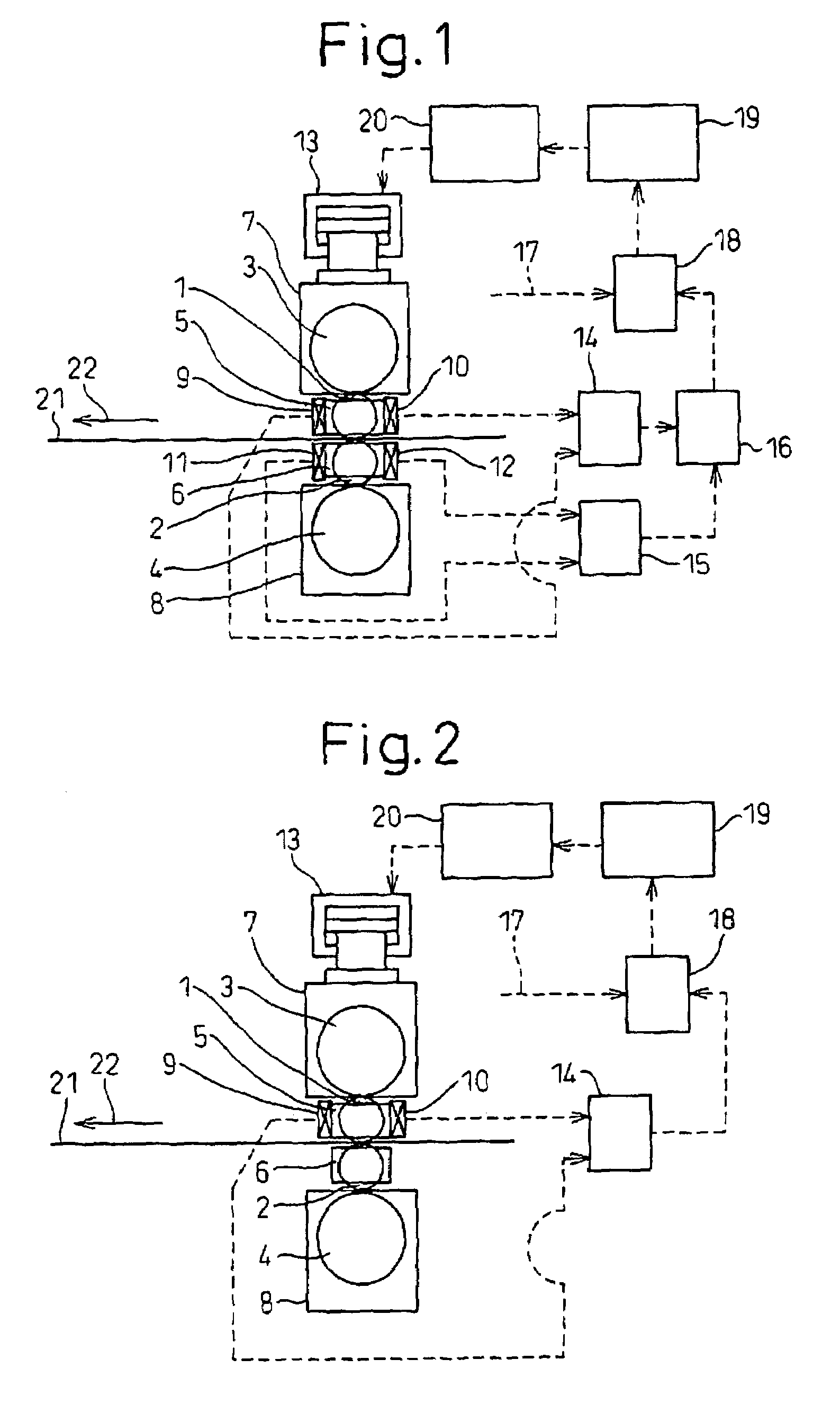
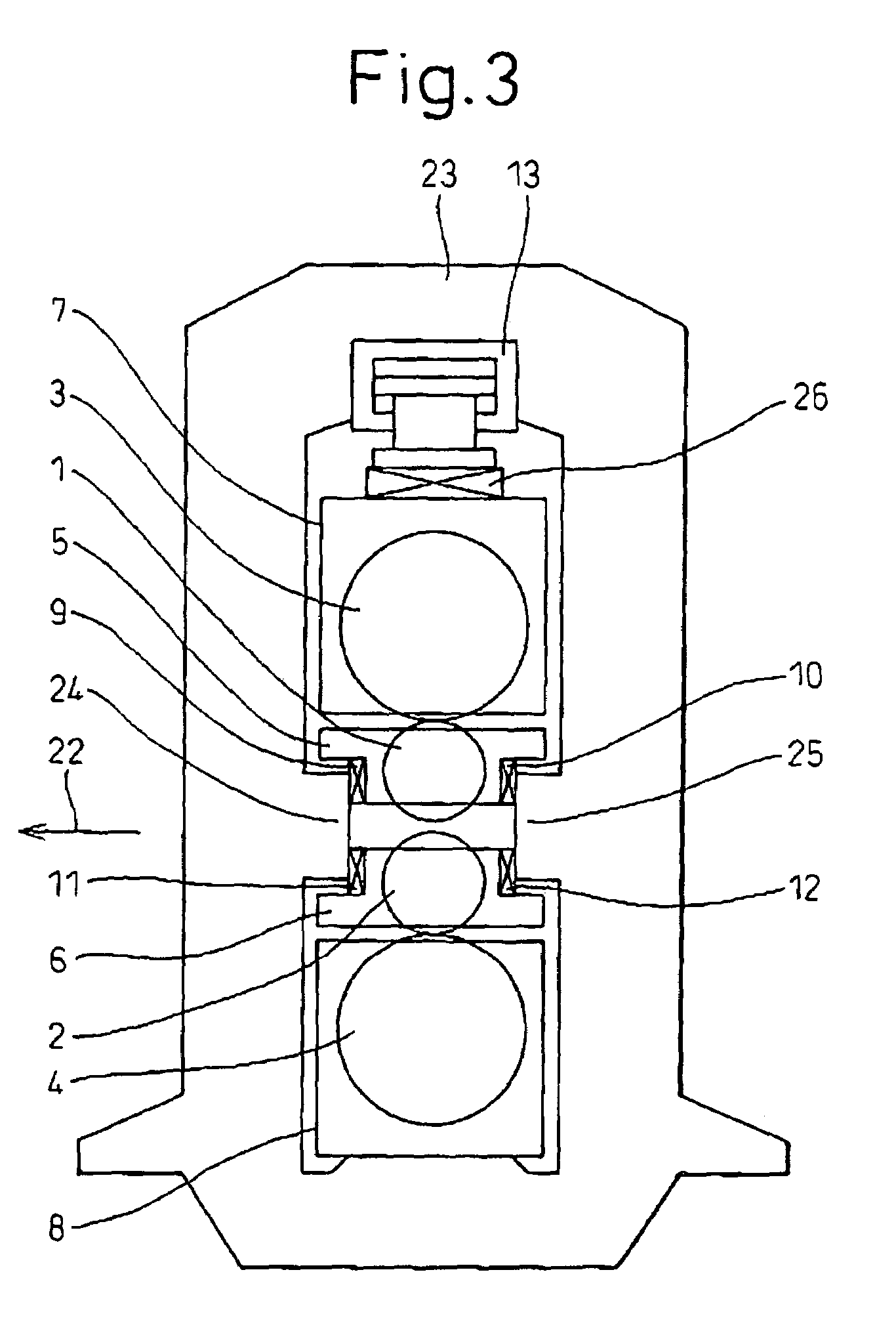
The invention provides a rolling method for a flat-rolled metal material and a rolling apparatus for the method each capable of stably producing a flat-rolled metal material free from camber or having an extremely light camber. The method is a rolling method of a flat-rolled metal material executed by using a rolling mill including at least work rolls and backup rolls. The apparatus is a rolling mill for this method. A rolling direction force acting on roll chocks on the operator side and the driving, side of the work roll is measured, the difference of the rolling direction force between the operator side and the driving side is calculated and a left-right swivelling component of roll gap of the rolling mill is controlled on the basis of this difference.

Description

TECHNICAL FIELD [0001]This invention relates to a rolling method and to a rolling apparatus for flat-rolled metal materials. More particularly, the invention relates to a rolling method and to a rolling apparatus, for flat-rolled metal materials that can stably produce flat-rolled metal materials not having, or having extremely light, camber.BACKGROUND ART[0002]In a rolling process of a flat-rolled metal material, it is very important to roll a sheet material in a form free from camber, or in a form not having bend in the left-right direction, in order to avoid not only a plane shape defect and a dimensional accuracy defect of the rolled material but also to avoid sheet pass troubles such as a zigzag movement and a tail crash.[0003]Incidentally, to simplify expressions, the operator side and the driving side of the rolling mill, as the right and left sides when the rolling mill is seen from the front of the rolling direction, will be called “right and left”, respectively.[0004]To co...

Claims


Application Information

Patent Timeline
Patent Type & Authority Patents(United States)
IPC IPC(8): B21B37/58B21B13/02B21B13/14B21B31/20B21B37/28B21B37/68B21B38/08
CPCB21B37/28B21B13/147B21B37/68B21B2273/04B21B2013/025B21B2031/206B21B38/08B21B37/30B21B37/22B21B37/48B21B37/58B21B38/06
Inventor OGAWA, SHIGERUISHII, ATSUSHIHIGASHIDA, YASUHIROHISATSUNE, TAKASHI
Owner NIPPON STEEL CORP
Learn More