
Roller mill roll bending and shifting device

A technology of roll bending and rolling mill, which is applied in the direction of metal rolling stand, metal rolling mill stand, metal rolling, etc., and can solve the problems of shortening the service life of work roll bearings, inability to achieve plate shape control, and eccentric load of work roll bearings , to achieve the effect of convenient assembly and disassembly of equipment, simple structure and avoiding partial load

Active Publication Date: 2008-05-28
CHINA ERZHONG GRP DEYANG HEAVY IND
View PDF0 Cites 23 Cited by
  • Summary
  • Abstract
  • Description
  • Claims
  • Application Information

AI Technical Summary

Problems solved by technology

The existing roll bending and shifting devices of rolling mills have two structures: one type of structure, the roll bending mechanism and the roll shifting mechanism are movable, and can move axially with the work roll device, this type of structure is complicated, and the hydraulic piping is complicated; the other type of structure is The roll bending mechanism is fixed and does not move axially with the work roll device, so the center of the bending force and the center of the work roll bearing deviates during roll shifting, causing eccentric loads on the work roll bearing, which greatly shortens the use of the work roll bearing life
The above two structures are almost impossible to realize the shape control of a rolling mill with a large opening and a large bending force.

Method used


Image

  • Roller mill roll bending and shifting device
  • Roller mill roll bending and shifting device
  • Roller mill roll bending and shifting device

Examples


Embodiment Construction

[0018] The present invention will be further described below in conjunction with the accompanying drawings and embodiments.

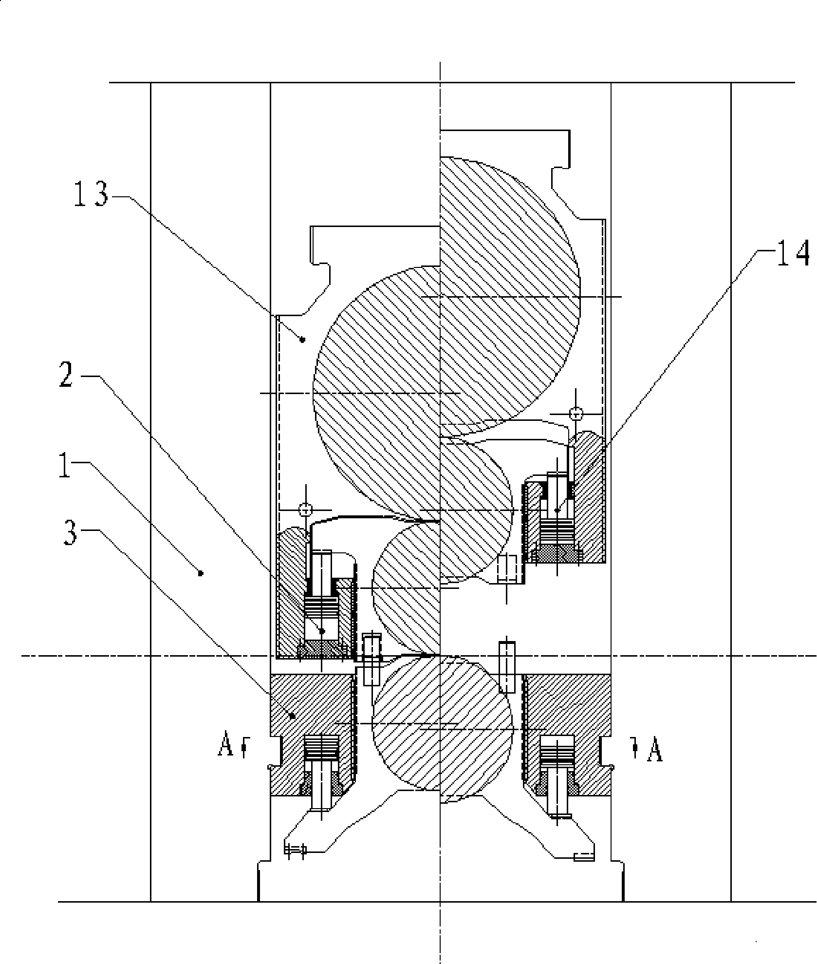
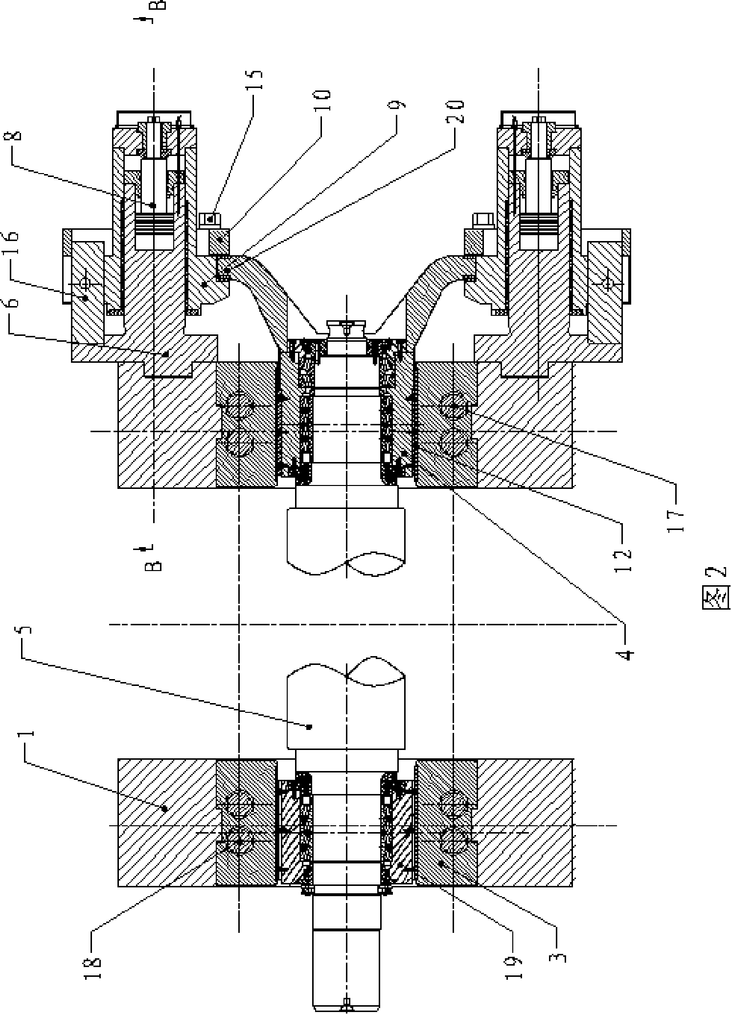
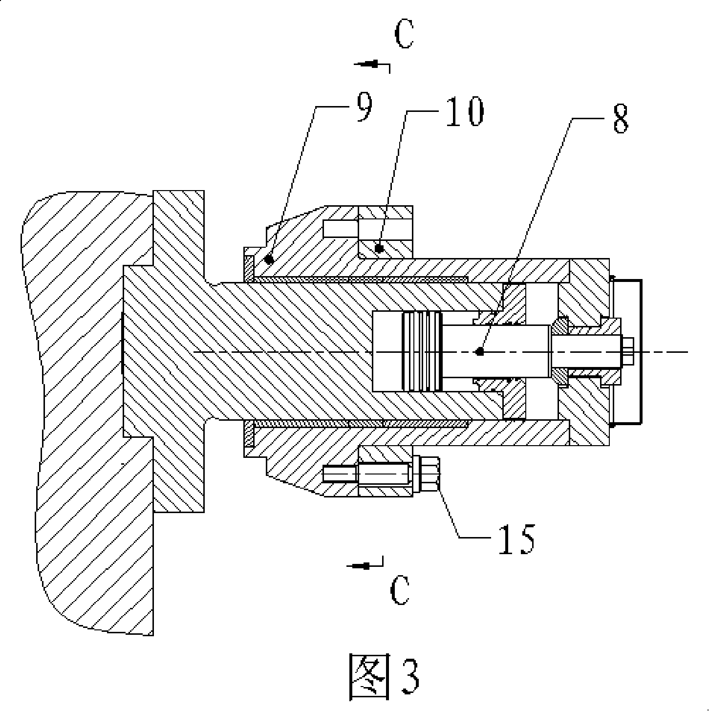
[0019] Such as figure 1 , Figure 2, Figure 3, Figure 4 As shown, the bending roll shifting device of the rolling mill of the present invention includes the upper roll bending hydraulic cylinders 2 and 14 on the operating side and the transmission side, the lower bending roll hydraulic cylinders 17 and 18, the bearing housings 4 and 19, and the stringing hydraulic cylinders on the operating side. Cylinder 8, roll shifting cylinder seat 6, frame 1 and work roll 5 set up and down; work roll 5 set up and down is installed on the bearing housing 4 and 19 on the operation side and the transmission side, and the bearing housing on the operation side and the transmission side 4 and 19 are axially movable relative to the frame 1, the upper bending hydraulic cylinder 2 and the lower bending hydraulic cylinder 17 on the operating side act radially on the bearing...


PUM


Abstract

The invention discloses a rolling mill bending roll and shift roll device, which has the advantage that a working roll bearing has no offset load moment when the roll is shifting. The rolling mill bending roll and shift roll device comprises upper bending roll hydraulic cylinders, lower bending roll hydraulic cylinders and bearing bases respectively arranged on the fore side and the backside, a shift roll hydraulic cylinder, a shift roll cylinder of the fore side, a frame work and a working roll arranged up and down; the working roll arranged up and down is installed on the bearing base of the fore side and the backside, the bearing base on the fore side and the backside is axially and movably arranged opposite to the frame work, the upper bending roll hydraulic cylinder and the lower bending roll hydraulic cylinder on the fore side is radially acted on the bearing base of the fore side, and the upper bending roll hydraulic cylinder and the lower bending roll hydraulic cylinder of the backside is radially acted on the bearing base of the backside, the shift roll hydraulic cylinder is distributed along the axes of the working roll and acted on he bearing base of the fore side, the upper bending roll hydraulic cylinders and the lower bending roll hydraulic cylinders of the fore side and the backside are fixedly arranged opposite to the frame work, and at least two of the upper bending roll hydraulic cylinders and the lower bending roll hydraulic cylinders are respectively arranged. The device can effectively avoid the offset load of the working roll bearing base, thus prolonging the service life.

Description

technical field [0001] The invention relates to a roll bending and stringing device for rolling mills in the metallurgical machinery industry, in particular to a bending and rolling device for large hot continuous rolling mills and medium and heavy plate rolling mills. Background technique [0002] At present, in the rolling process of the rolling mill, in order to achieve the purpose of controlling the shape and improving the quality of the shape during the rolling process, it is necessary to rely on the roll bending device to make the work rolls in the upper work roll device and the lower work roll device, the upper work roll The backup rollers in the backup roller device and the lower backup roller device are bent to a certain extent. After rolling for a period of time, in order to improve the wear condition of the work rolls, it is necessary to rely on the roll shifting device to realize the axial movement of the upper and lower work rolls, thereby increasing the service...

Claims


Application Information

Patent Timeline
IPC IPC(8): B21B31/16B21B37/42
Inventor 刘勇安陈建平钟晓兵
Owner CHINA ERZHONG GRP DEYANG HEAVY IND
Learn More