Photoelectric encoder
a technology of photoelectric encoder and encoder, applied in the direction of converting sensor output optically, instruments, measurement devices, etc., can solve the problems of image division and reverse in each single lens optical system
- Summary
- Abstract
- Description
- Claims
- Application Information
AI Technical Summary
Benefits of technology
Problems solved by technology
Method used
Image
Examples
first embodiment
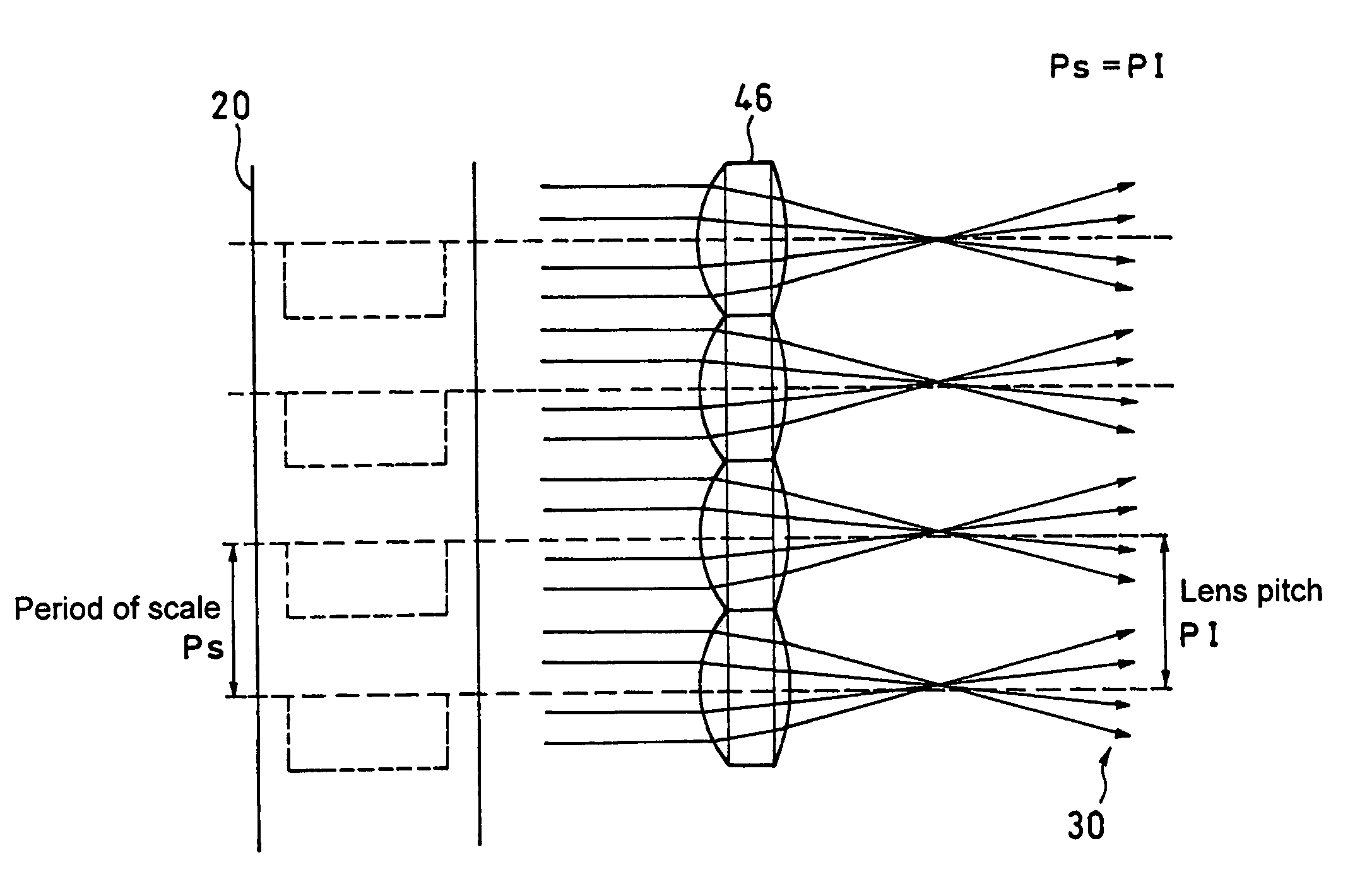
[0051]As shown in FIG. 6, according to the present invention, an incremental type photoelectric encoder has a lens array 46. The lens array 46 is composed of a plurality of lenses with a set pitch P1 (referred to as “lens pitch”) which is brought into agreement with a period Ps of a main scale 20 or natural number multiple thereof.
[0052]As shown in FIG. 7, in the present embodiment since the pattern is ensured even if the image is divided and reversed in each separate lens, there is no problem as long as it is used as an incremental type.
[0053]Further, as shown in FIG. 8, aperture 44 can be provided at focal point of each lens of the lens allay 46 so as to form a telecentric optical system 40.
second embodiment
[0054]Next, the present invention will be described with reference to FIG. 9 (light path view) and FIG. 10 (perspective view).
[0055]In the present embodiment, a second lens array 48 identical to the lens array 46 (first lens array) is provided in the reverse direction so as to make the focal points thereof be positioned at the positions where the focal points of the first lens array 46 are located, thereby forming an optical system 50.
[0056]In the present embodiment, the lens array 48 is the same as the lens array 46. Because of this, aberrations occurring on the first lens array 46 provided on the input side can be almost completely inversely corrected by the second lens array 48 provided on the output side. Therefore, even if a low-cost lens array with large aberrations is used, the aberrations can be almost completely cancelled and the signal detection efficiency can be greatly improved.
[0057]Further, as shown in FIGS. 11 and 12, aperture 44 can be provided at focal point of each...
third embodiment
[0058]Next, the present invention will be described with reference to FIG. 13.
[0059]The present embodiment relates to an absolute type photoelectric encoder that has a lens array 46. In this photoelectric encoder, an image is electrically re-reversed by changing the output connection of a light receiving element array 34 by the pixels.
[0060]Further, as shown in FIG. 14, aperture 44 can be provided at focal point of each lens of the lens allay 46 so as to form a telecentric optical system 40.
PUM
 Abstract
Description
Claims
Application Information
 - R&D
- Intellectual Property
- Life Sciences
- Materials
- Tech Scout
- Unparalleled Data Quality
- Higher Quality Content
- 60% Fewer Hallucinations
Browse by: Latest US Patents, China's latest patents, Technical Efficacy Thesaurus, Application Domain, Technology Topic, Popular Technical Reports.
© 2025 PatSnap. All rights reserved.Legal|Privacy policy|Modern Slavery Act Transparency Statement|Sitemap|About US| Contact US: help@patsnap.com


