
Method for completing a well using increased fluid temperature

a technology of fluid temperature and wellbore, which is applied in the direction of wellbore/well accessories, chemistry apparatus and processes, etc., can solve the problems of limiting the need for weighted drilling fluid, reducing and reducing the safety of personnel on the rig floor, so as to increase the fracture resistance of the formation

Inactive Publication Date: 2007-12-11
WEATHERFORD TECH HLDG LLC
View PDF80 Cites 18 Cited by
  • Summary
  • Abstract
  • Description
  • Claims
  • Application Information

AI Technical Summary

Benefits of technology

[0016]The present invention generally provides methods for forming a portion of a wellbore. In one embodiment, the method includes the steps of drilling a well from a first selected depth to a second selected depth to form a bore through a surrounding earth formation, disposing a fluid heating apparatus in the bore, heating fluid by moving the fluid through the fluid heating apparatus, and heating the surrounding earth formation by circulating the heated fluid adjacent the earth formation so as to increase the fracture resistance of the formation. Preferably, the fluid heating apparatus is a fluid flow restrictor.
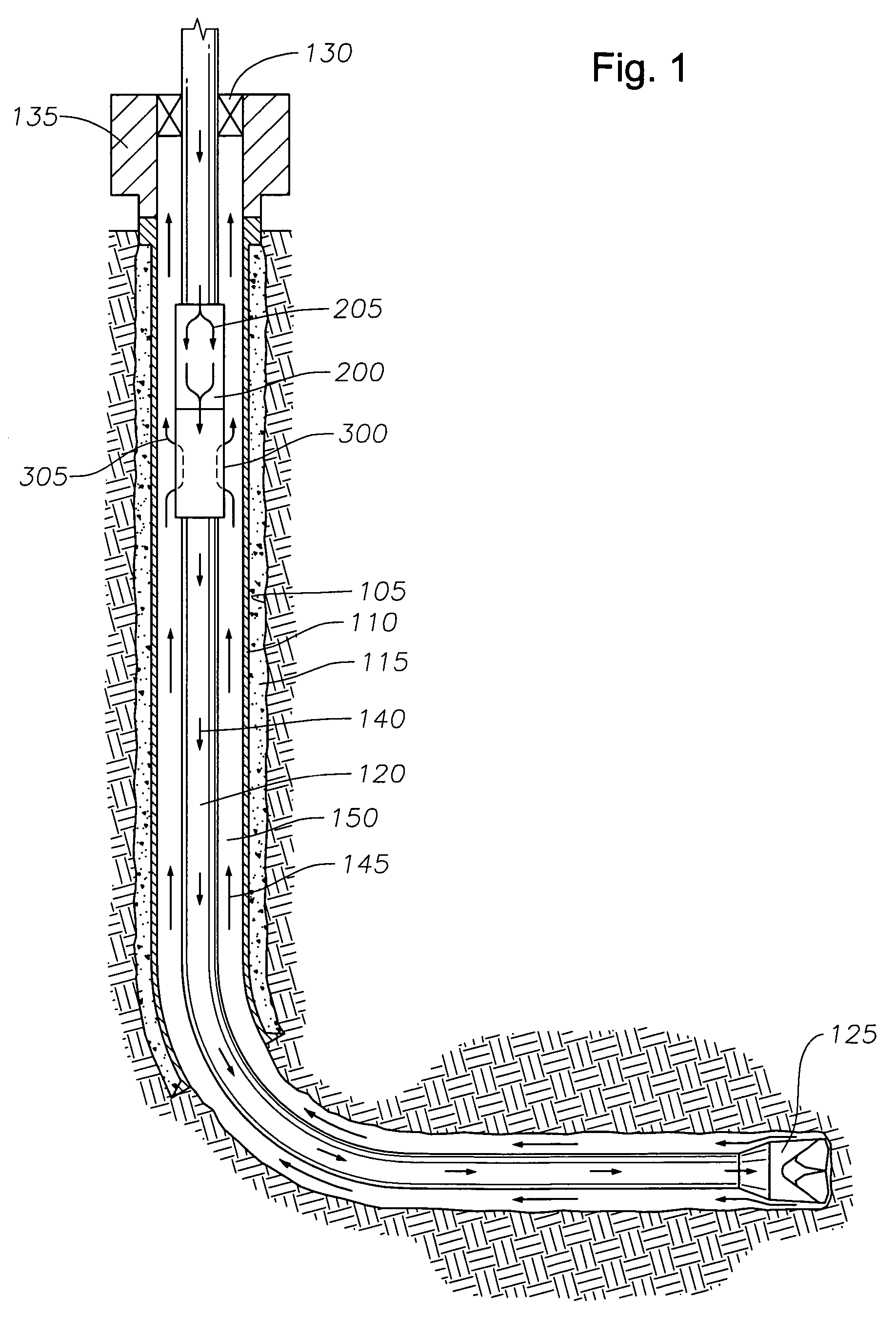
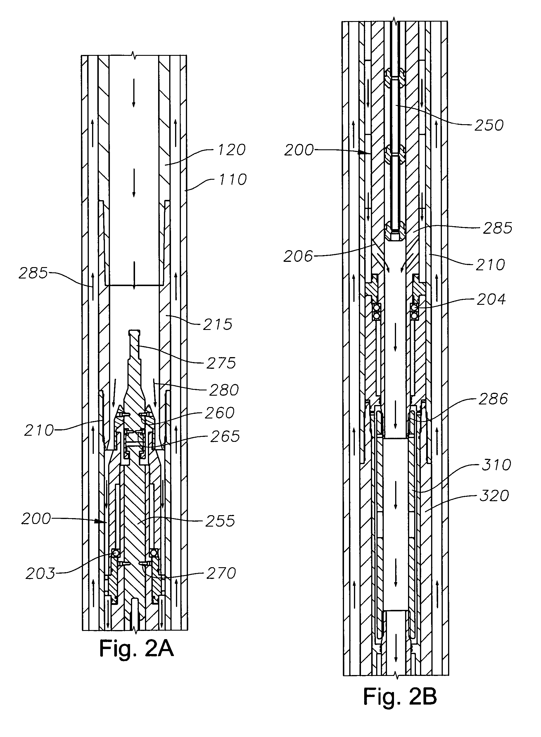
[0025]In one aspect of the inventions, an ECD (equivalent circulation density) reduction tool provides a means for drilling extended reach deep (ERD) wells with heavyweight drilling fluids by reducing the effect of the hydrostatic head on bottomhole pressure so that circulating density of the fluid is close to its actual density. With an ECD reduction tool located in the well, the hydrostatic head is substantially reduced, which in turn reduces the risk of fracturing a formation. At the same time, the ECD reduction tool increases the temperature of the fluid before it contacts the surrounding earth formation at the bottom of the wellbore. The increased temperature serves to increase formation fracture resistance. This, in turn, allows the formation to tolerate a greater ECD so that more earth can be penetrated during drilling between casing stages. The number of casing sizes required to complete the well is thereby reduced. This is particularly helpful in those circumstances where casing shoe depth is limited by a narrow margin between pore pressure and fracture pressure of the formation.

Problems solved by technology

One such limiting factor is the need for weighted drilling fluid.
Exceeding fracture pressure can result in fracturing of the formation and loss of expensive drilling fluid into the formation.
More importantly, lost circulation creates a risk to personnel on the rig floor, as the rig is now subject to a “kick” caused by formation pore pressures.
The use of drilling mud and the resulting ECD create an inherent limitation as to the depth at which any section of borehole may be drilled before it must be cased.
Presently, however, with extended reach drilling (ERD) wells, so many casing strings are necessary that the fluid path for hydrocarbons at a lower portion of the wellbore becomes very restricted.
While this device stirs up and agitates wellbore fluid, it does not provide any meaningful lift to the fluid in order to reduce the pressure of fluid there below.
A similar issue may be confronted during a cementing operation.
These factors also may limit the length of liner that can be cemented in one completion stage.

Method used


Image

  • Method for completing a well using increased fluid temperature
  • Method for completing a well using increased fluid temperature
  • Method for completing a well using increased fluid temperature

Examples


Embodiment Construction

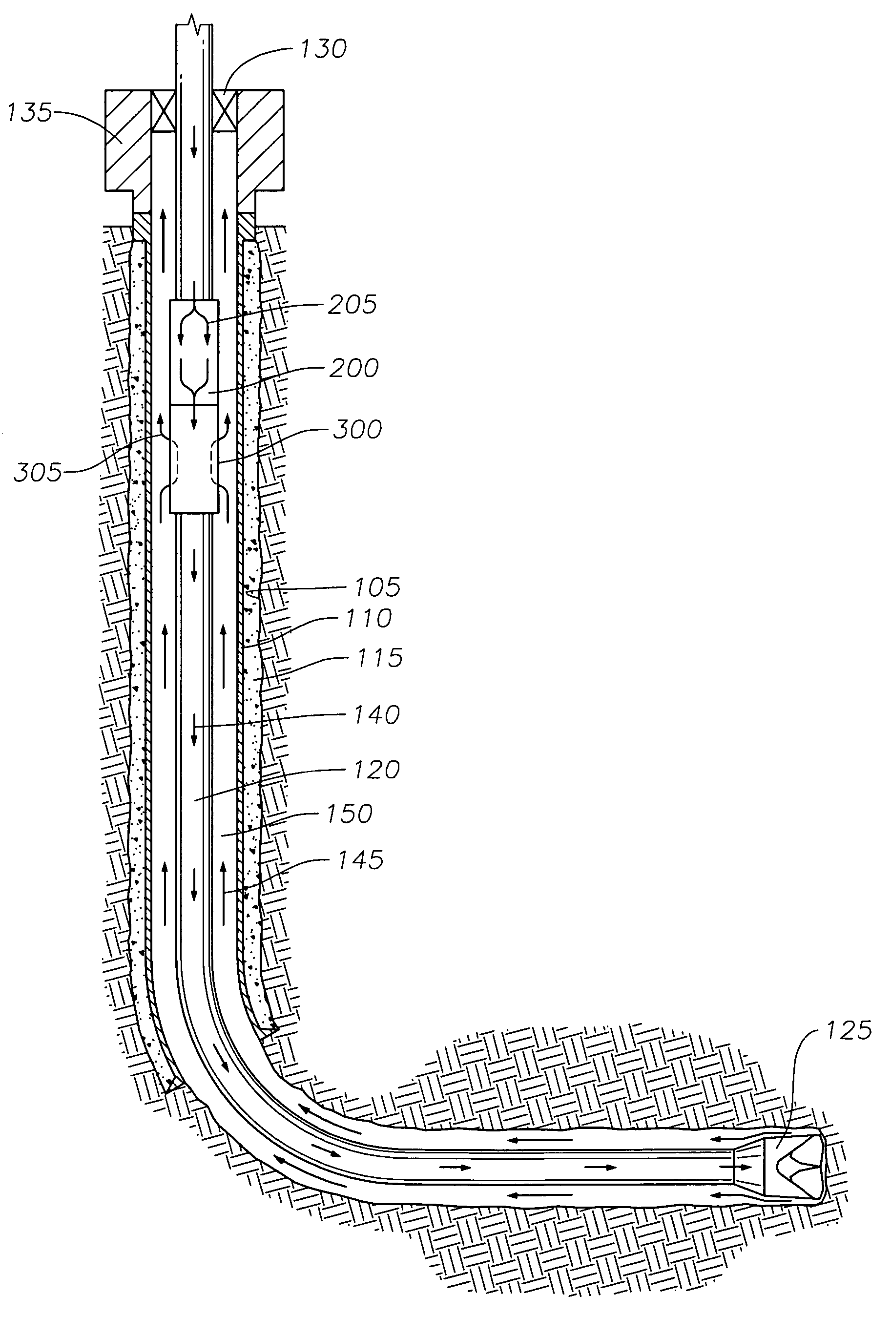
[0051]The present invention relates to various methods for completing a wellbore. The various methods may first be understood in the context of the exemplary wellbore 105 found in FIG. 1. The wellbore 105 of FIG. 1 comprises a central portion and a horizontal portion, though the present methods may be employed in a wellbore of any configuration. The central wellbore is lined with casing 110. An annular area between the casing 110 and the surrounding earth formation 50 is filled with cement 115 to strengthen and isolate the central wellbore 105 from the earth.

[0052]At a lower end of the central wellbore, the casing 110 terminates. The horizontal portion of the wellbore 105 extends below the central portion. The horizontal bore opens into an “open hole” portion. This means that the lower portion of the illustrative wellbore 105 is uncased.

[0053]A working string 120 is placed within the wellbore 105. The working string 120 resides generally coaxially in the wellbore 105, and is made up...


PUM


Abstract

Methods for forming a portion of a wellbore are provided. The well is drilled from a first selected depth to a second selected depth to form a bore through a surrounding earth formation. A fluid heating apparatus is disposed within the bore on a working string. Fluid is then heated by moving the fluid through the fluid heating apparatus in the wellbore. The process of circulating fluid adjacent the earth formation serves to also heat the surrounding formation so as to increase the fracture gradient. The fluid heating process may be conducted during a drilling procedure. Alternatively, the fluid heating process may be conducted in connection with a liner hanging and cementing process. A fluid flow restrictor is provided along a run-in assembly that serves to warm the fluids as they are circulated. The warm fluids provide convective heat to the surrounding earth formation, thereby reducing the formation's fracture gradient.

Description

CROSS-REFERENCE TO RELATED APPLICATIONS[0001]This application is a continuation-in-part of U.S. patent application Ser. No. 10 / 156,722, filed May 28, 2002, now U.S. Pat. No. 6,837,313 which is incorporated by reference herein in its entirety. That application is entitled “Apparatus and Method to Reduce Fluid Pressure in a Wellbore.”[0002]That application, in turn, was a continuation-in-part of U.S. patent application Ser. No. 09 / 914,338, filed Jan. 8, 2002. That application has since matured into U.S. Pat. No. 6,719,071, and is likewise incorporated herein by reference.BACKGROUND OF THE INVENTION[0003]1. Field of the Invention[0004]The present invention relates to the completion of a wellbore. More particularly, the invention relates to methods for completing a hydrocarbon wellbore that involve heating of circulating fluid to increase formation fracture pressure in the surrounding formation during drilling, cementing and completion operations.[0005]2. Description of the Related Art[...

Claims


Application Information

Patent Timeline
Patent Type & Authority Patents(United States)
IPC IPC(8): E21B43/24E21BE21B21/00E21B21/06E21B21/08E21B36/00
CPCE21B21/08E21B43/10E21B36/006E21B2021/006E21B21/085E21B21/003E21B36/04
Inventor BANSAL, R. K.BRUNNERT, DAVID J.GRAYSON, MICHAEL BRIANWHANGER, JAMES KENLOWE, EVANGHARESI, ABDOLREZAHANBERRY, TIM
Owner WEATHERFORD TECH HLDG LLC
Learn More