Electrophoretic particles, electrophoretic dispersion liquid, and electrophoretic display device
a technology of electrophoretic dispersion liquid and electrophoretic particles, which is applied in the field of electrophoretic display devices, can solve the problems of conventional electrophotographic particles accompanied by problems, poor viewability of characters on picture areas, and insufficient solution of light sources, so as to improve the response speed of electrophotographic particles, improve charging performance, and improve the dissociation characteristic
- Summary
- Abstract
- Description
- Claims
- Application Information
AI Technical Summary
Benefits of technology
Problems solved by technology
Method used
Image
Examples
example 1
[0118]A uniform mixture liquid was prepared by mixing 15 g of titanium oxide particles (average particle size: 0.2 μm) which were subjected to hydrophobicity-imparting treatment and 1.7 g of azobisisobutyronitrile (AIBN) (polymerization initiator) in 7 g of methacrylic acid and 130 g of methyl methacrylate. In a dispersion medium comprising 1800 g of a sodium dodecyl sulfonate aqueous solution (concentration: 0.05 wt. %) and 90 g of calcium phosphate dispersed therein, the uniform mixture liquid was added. The resultant liquid was stirred at 10,000 rpm for 15 minutes by a homogenizer to prepare a suspension. Thereafter, the suspension was subjected to polymerization at 80° C. for 7 hours in a nitrogen atmosphere. After the polymerization, the resultant polymer particles were washed, followed by drying and classification to obtain white particles each comprising titanium oxide particle coated with (methacrylic acid-methyl methacrylate) copolymer. An average particle size of the parti...
example 2
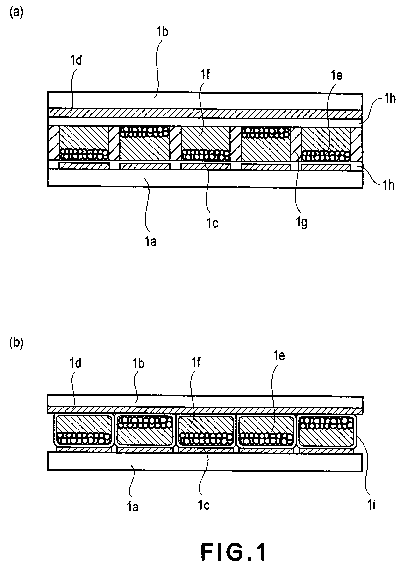
[0124]A plurality of microcapsules 1i each containing an electrophoretic dispersion liquid prepared in the same manner as in Example 1 were prepared by in-situ polymerization method. Each microcapsule was formed of urea-formaldehyde resin as a film-forming material. An electrophoretic display device shown in FIG. 1(b) was prepared by disposing the plurality of microcapsules 1i on a first substrate 1a by use of nozzles according to the ink jet method. The electrophoretic display device was connected with a voltage application circuit.
[0125]As a result of measurement of electric conductivity, it was confirmed that a degree of dissociation of the imidazolium salt of the electrophotographic particles 1e was about 80 times that of an electrifying agent used in Comparative Example 1 appearing hereinafter, thus resulting in an excellent dissociation characteristic.
[0126]When the resultant electrophoretic display device was subjected to contrast display by driving it at a low voltage of ±5 ...
example 3
[0127]Particles of titanium oxide, coated with (methacrylic acid-methyl methacrylate) copolymer, prepared in the same manner as in Example 1 was subjected to two-stage polymerization with 2-ethylhexyl methacrylate to form a core-shell structure wherein a steric hindrance group was introduced into a surface of particle.
[0128]With 10 g of the thus obtained particles, 1.2 g of a pyridinium salt represented by a structural formula (B) shown below was caused to react in methanol, followed by separation and purification to obtain electrophotographic particles 1e each having the pyridinium salt.
Formula (B):
[0129]
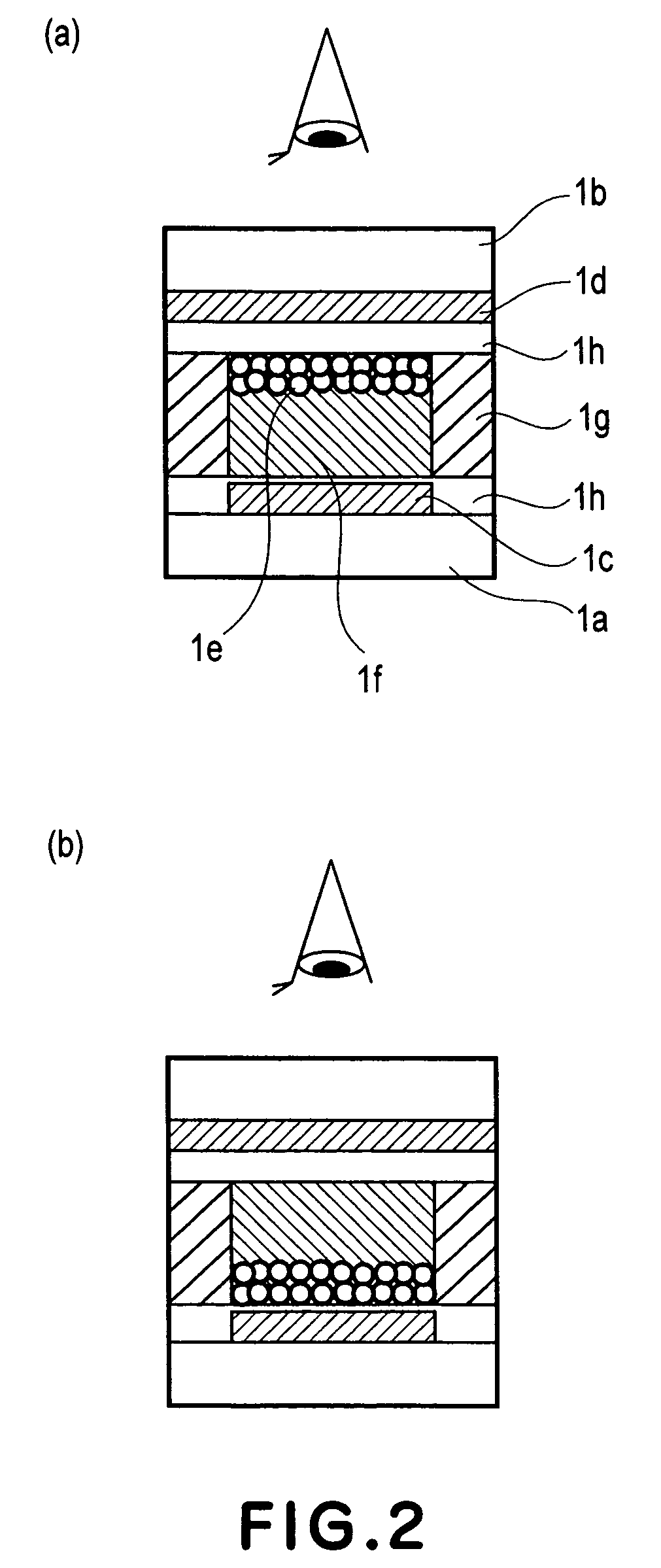
[0130]Then, 5 wt. % of the white electrophoretic particles 1e and 95 wt. % of an electrophoretic dispersion medium 1f comprising isoparaffin (trade name: “Isoper H”, mfd. by Exxon Corp.) colored blue with 0.1 wt. % of a colorant (“Oil Blue N”, mfd. by Aldrich Co.) dissolved therein, were mixed to prepare an electrophoretic dispersion liquid. The electrophoretic dispersion liquid wa...
PUM
| Property | Measurement | Unit |
|---|---|---|
| particle size | aaaaa | aaaaa |
| particle size | aaaaa | aaaaa |
| particle size | aaaaa | aaaaa |
Abstract
Description
Claims
Application Information
 - R&D
- Intellectual Property
- Life Sciences
- Materials
- Tech Scout
- Unparalleled Data Quality
- Higher Quality Content
- 60% Fewer Hallucinations
Browse by: Latest US Patents, China's latest patents, Technical Efficacy Thesaurus, Application Domain, Technology Topic, Popular Technical Reports.
© 2025 PatSnap. All rights reserved.Legal|Privacy policy|Modern Slavery Act Transparency Statement|Sitemap|About US| Contact US: help@patsnap.com


