
Pressure gradient dosing system for fluid supply

a fluid supply system and pressure gradient technology, applied in the direction of liquid displacement, separation process, other chemical processes, etc., can solve the problems of increasing wear on the diesel engine, affecting the overall operation, performance and efficiency of the engine, and even the environment, so as to reduce the prevent damage to the engine and other downstream components, and enhance the engine's performance

Active Publication Date: 2007-11-20
CUMMINS FILTRATION INC
View PDF34 Cites 11 Cited by
  • Summary
  • Abstract
  • Description
  • Claims
  • Application Information

AI Technical Summary

Benefits of technology

The patent text describes a new system for adding additives to fluids, such as fuel, to improve their performance and reduce damage to the engine. The system uses a pressure gradient to continuously add the additive to the fluid as it flows through a filter. This allows for a consistent and desired level of additive in the fluid. The system can be used in filter assemblies for fuel, hydraulic filters, lubricant filters, and coolant filters. The technical effect of this system is improved performance and reliability of the engine, reduced wear and damage to downstream components, and improved fuel quality.

Problems solved by technology

The resulting low sulfur content diesel fuel caused increased wear on the diesel engine and, in particular, to the fuel pump and injectors, which in turn caused significant harm to the overall operation, performance, and efficiency of the engine and even to the environment.
It is difficult to maintain a constant or desired level of the additive in the fuel.
While many bottled fuel additives are commercially available, often operators do not consistently add the additive with each fill-up—the additive might not be readily available or the operator may forget to include the additive.
Combining the additive with fuel in the fuel tank may not reliably provide a homogenous fuel / additive mixture.
Fuel tanks do not include reliable methods for mixing fuel.
Pressure gradient slow release filters have a liquid capacity to perhaps treat fuel for 5,000 miles (approximately 600 to 800 gallons of fuel), and hence filter capacity is a limiting factor in drain intervals.
Current pressure gradient filters are limited for use in low mileage, low hour operating applications, such as beverage delivery trucks, refuse collection trucks, etc., and cannot effectively be used on heavy duty on-highway fleet applications.
Furthermore, lubricity currently has a limitation of approximately 500 hours of operation, and a remote mounted dosing canister could double the preventative maintenance cycle.

Method used


Image

  • Pressure gradient dosing system for fluid supply
  • Pressure gradient dosing system for fluid supply
  • Pressure gradient dosing system for fluid supply

Examples


Embodiment Construction

Parent Applications

[0075]The following section is taken from the above noted parent applications.

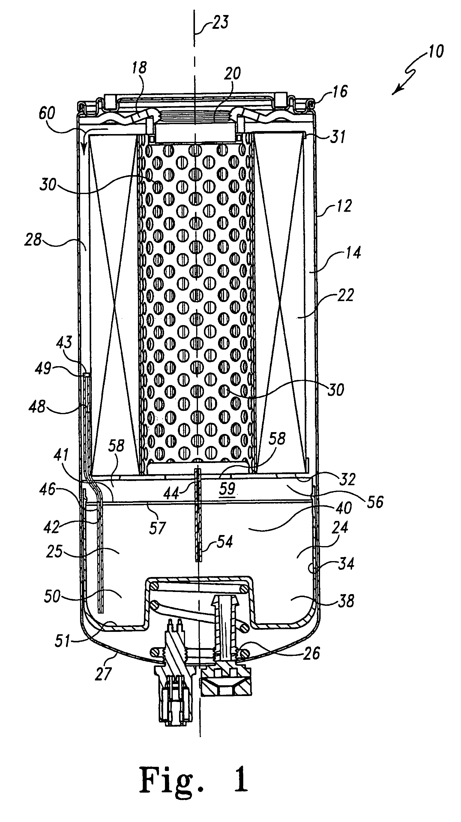
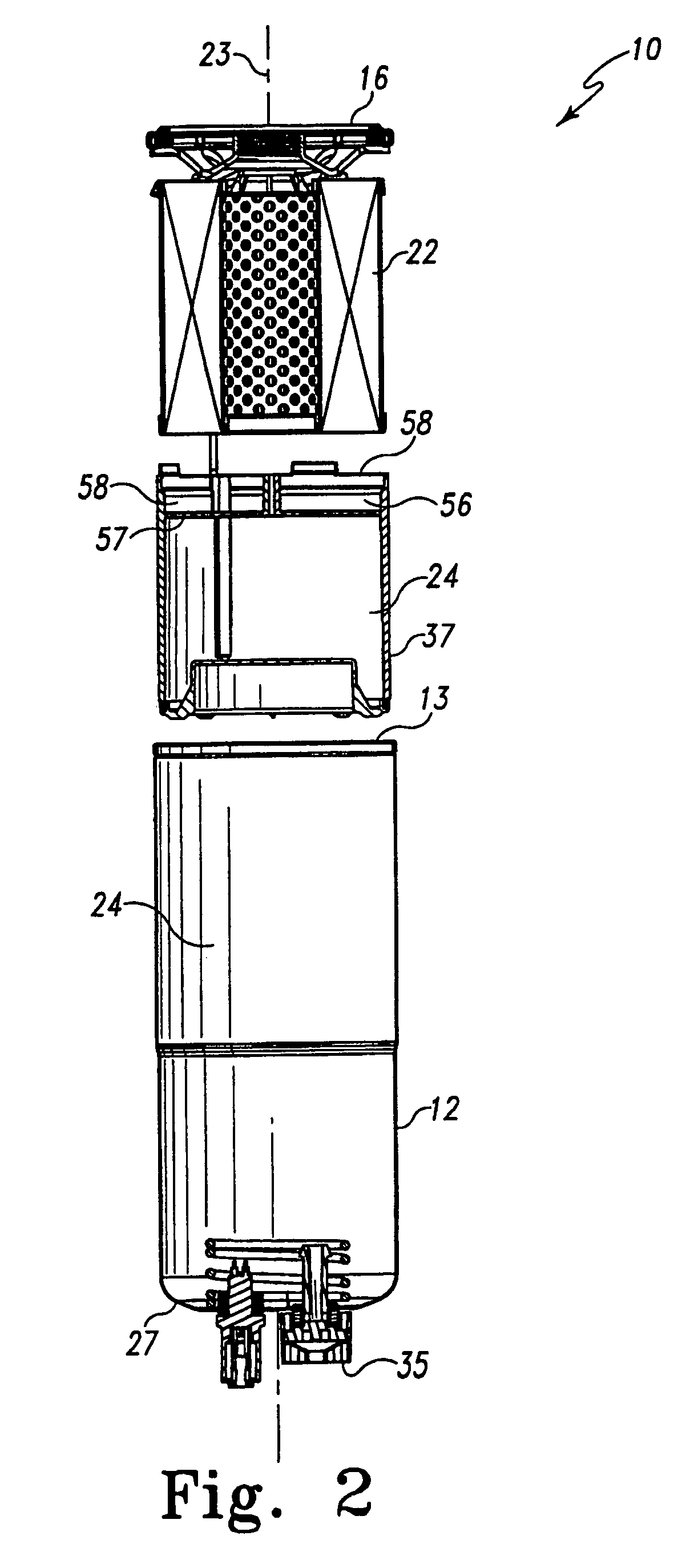
[0076]For the purposes of promoting an understanding of the principles of the parent applications, reference will now be made to the embodiments illustrated herein, and specific language will be used to describe the same. It will nevertheless be understood that no limitation of the scope of the parent applications is thereby intended. Any alterations and further modifications of the described filters, cartridges, and processes, and any further applications of the principles of the parent applications as described herein, are contemplated as would normally occur to one skilled in the art to which the parent applications relate.

[0077]FIG. 1 is a cross-sectional view of a filter assembly 10 provided in accordance with the parent applications. FIG. 2 is an exploded, cross-sectional view of the same filter assembly 10. Filter assembly 10 includes a housing or outer casing 12 defining an inter...


PUM

PropertyMeasurementUnit
diameteraaaaaaaaaa
diameteraaaaaaaaaa
diffusion coefficientaaaaaaaaaa

Abstract

A pressure gradient dosing system is provided for a fluid supply system. A flow passage has first and second pressure zones having a pressure gradient therebetween. An additive reservoir in an additive delivery system responds to the pressure gradient to release additive to the flow passage.

Description

CROSS-REFERENCE TO RELATED APPLICATIONS[0001]This application is a continuation-in-part of U.S. patent application Ser. No. 10 / 956,408, filed Sep. 30, 2004, now U.S. Pat. No. 7,153,422, and a continuation-in-part of U.S. patent application Ser. No. 10 / 767,513, filed Jan. 29, 2004, now U.S. Pat. No. 7,156,991. The '408 application is a continuation-in-part of the '513 application.BACKGROUND AND SUMMARY[0002]The invention relates to fluid supply systems, and more particularly to a pressure gradient dosing system for a fluid supply system.PARENT APPLICATIONS[0003]The following section is taken from the above noted parent applications.[0004]The parent inventions are directed to a liquid filtration system and to a method of treating the liquid in the enclosed system.[0005]Filter assemblies are commonly used to protect combustion engines by filtering out contaminants and thereby preventing damage to the engine and other downstream components such as valves, fuel injectors, fuel lines, and...

Claims


Application Information

Patent Timeline
Patent Type & Authority Patents(United States)
IPC IPC(8): B01D11/00B01D12/00B01D29/11B01D27/00B01D27/04B01D29/07B01D37/02
CPCB01D27/00B01D29/21B01D37/025B01D29/96Y10T137/4891
Inventor LOFTIS, TED S.BRISK, DAVID L.VERDEGAN, BARRY M.MARTIN, JR., HAROLD R.HERMAN, PETER K.BAGCI, ISMAIL C.TRUE-DAHL, ABBY
Owner CUMMINS FILTRATION INC
Learn More