
SVC signaling system and method

a signaling system and signaling method technology, applied in the field of scalable network devices, can solve the problems of slow modems, inability to fully capture digital audio and video services to the satisfaction of end users, and limited bandwidth on the loop side for today's traffic needs, etc., to achieve the effect of improving performance, documentation and reporting

Inactive Publication Date: 2007-11-13
RPX CLEARINGHOUSE
View PDF4 Cites 92 Cited by
  • Summary
  • Abstract
  • Description
  • Claims
  • Application Information

AI Technical Summary

Benefits of technology

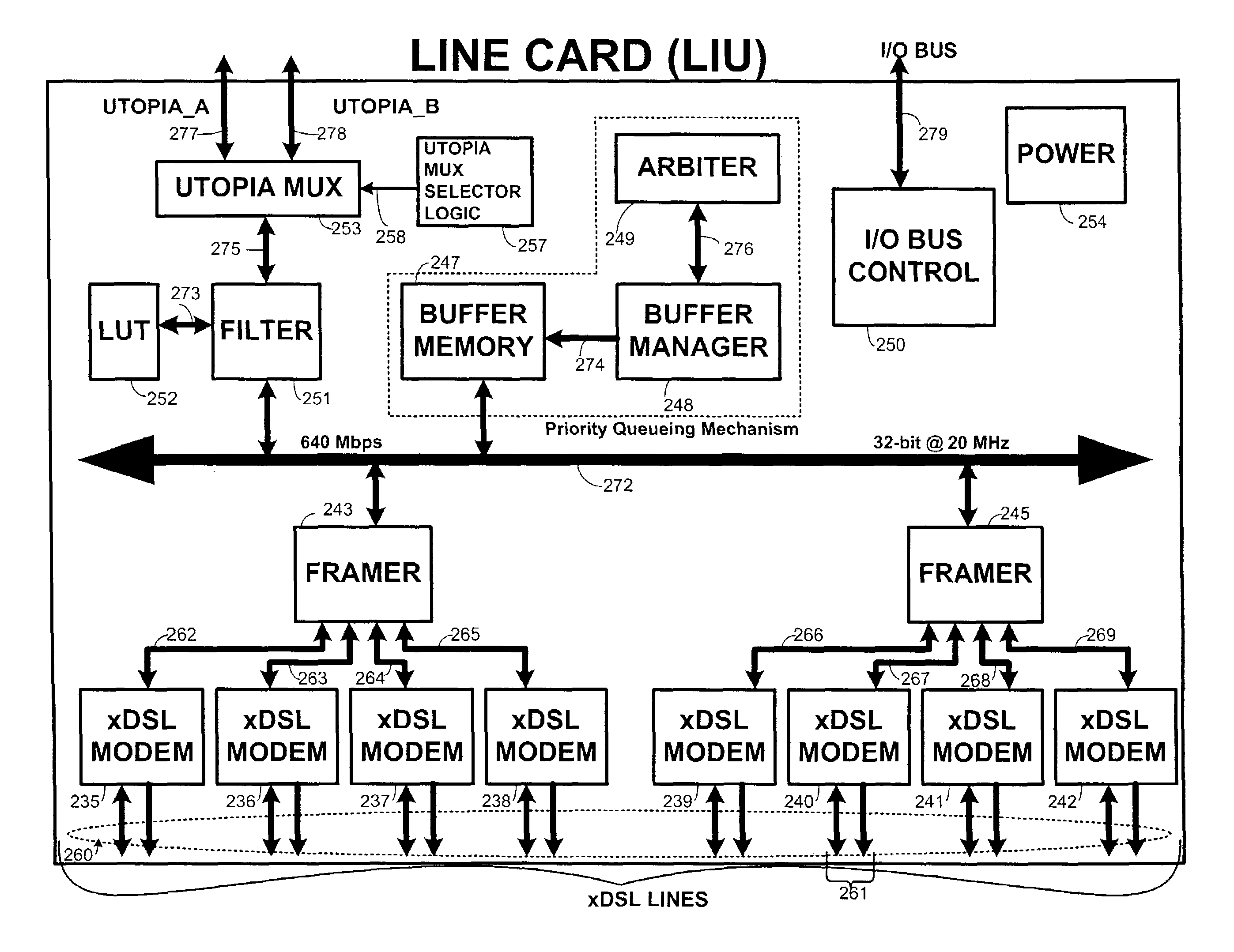
[0039]In the upstream direction, assume that each line card having eight DSL ports are fully loaded. At 640 Kbps per ADSL line upstream, each line card receives an aggregate of 5.12 Mbps data (640 Kbps×8 ports per line card). For eighteen line cards, the aggregate bandwidth delivered to the chassis switch cards is 92.16 Mbps (5.12 Mbps×18 line cards). Each line card-side port in the chassis switch card supports 155 Mbps and the shared bus supports 640 Mbps. The output telecommunications backbone side port also supports 155 Mbps data. Thus, the 92.16 Mbps upstream data from the line cards reaches and makes its way out of the chassis switch card uncongested. As illustrated by this example, this non-blocking feature practically minimizes or eliminates oversubscription for some IMAS configurations.
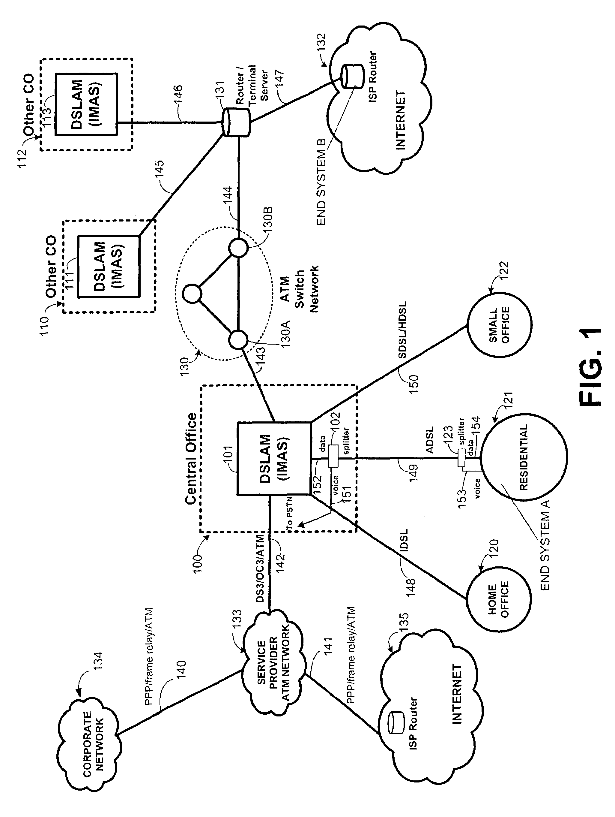
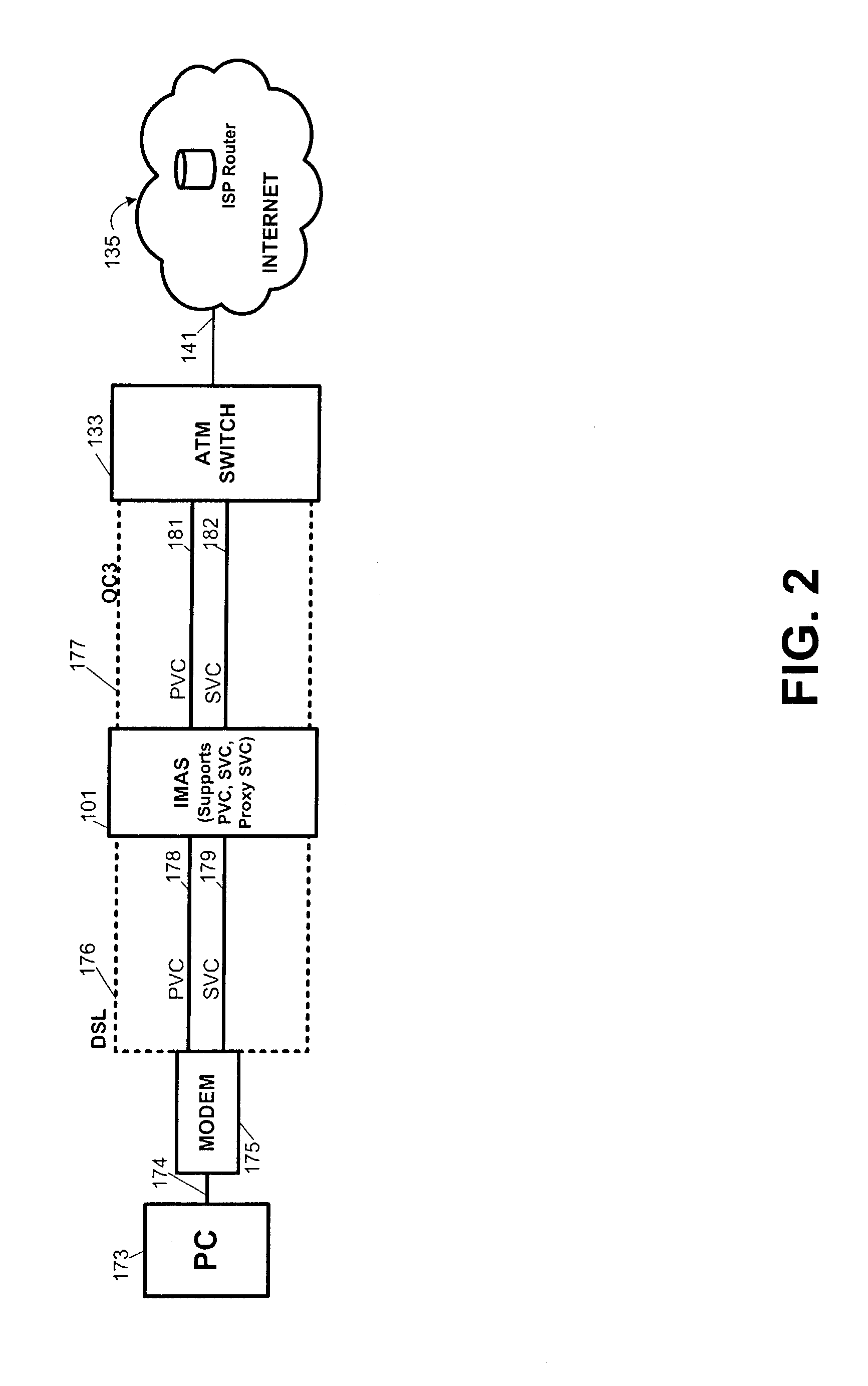
[0042]For these non-signaling end systems, SVCs can still be supported using the proxy signaling aspect of the present invention. The proxy signaling aspect of the present invention uses a proxy signaling agent at the IMAS to control the virtual connection / circuit setup and termination of the non-signaling ATM end system. As mentioned above, proxy signaling calls are made on behalf of xDSL associated devices (e.g., ADSL modems) at the subscriber's side because these devices currently do not support SVC signaling. The proxy signaling agent residing in the IMAS allows those PVC-supported calls directed to the OC3 uplink to be supported by SVC so that session-based virtual paths can be established as needed, without waiting valuable time for a PVC path to be established. As soon as the call (including the SVC signaling) is successful, a data connection is set up between the xDSL port at the IMAS in the central office and the OC3 uplink port. Similarly, an SVC call that had previously been established can be torn down via the same SVC signaling.
[0046]Representative tasks performed by the NMS include actively monitoring network resources for the purpose of device configuration, troubleshooting, detecting potential problems, improving performance, documentation, and reporting. The network management system performs other tasks including, but not limited to, autodiscovery of devices on the network; network topology mapping in the form of a graphic map that can be zoomed in or out; and the ability to schedule management tasks or jobs at specific times or dates. Other tasks include data backup, providing security, training users, and setting policies.

Problems solved by technology

Although the bandwidth on the telecommunications backbone (e.g., DS3, OC3, STS3, or OC12) may be sufficient for all of the various types of traffic generated by subscribers, the bandwidth on the loop side is limited for today's traffic needs.
However, with the rise of the Internet and the increased interest in digital video and audio services, earlier modems were sorely lacking as speeds were as low as 1,200 bits / sec (V.22) to 33.6 Kbits / sec (V.34+) to today's 56 Kbits / sec (U.S. Robotics / 3COM and Lucent / Rockwell).
Even at 56 Kbits / sec, these modems are still too slow to fully capture digital audio and video services to the end user's satisfaction.
Even if modems could use all of the available 64 Kbits / sec bandwidth provided by the telephone company, users would still be dissatisfied for the latest audio and video digital services.
One such loop technology is ISDN (at 128 Kbits / sec), which failed to deliver on its promise of better digital service because of the high cost of ISDN equipment and the higher cost of upgrading central office hardware and software.
Furthermore, ISDN equipment was difficult to set up and make compatible with existing equipment because of poor diagnostics.
However, their prohibitively high expense makes these line technologies less attractive to the average subscriber.
However, DSL may not eliminate other technologies (e.g., T1, T3, ISDN, and cable modem) as the various telephone companies will make these technologies available to those who want them and can afford them.
However, current DSLAMs are limited.
Although the various types of DSL technologies will be implemented, most existing DSLAMs cannot support multiple DSL technologies; that is, a given DSLAM can only support one DSL technology.
This limits what the telecommunications providers are willing to do to expand DSL throughout their respective network.
Given the shortage of space in central offices today, telecommunications service providers may be unwilling to purchase multiple DSLAMs for all the different types of DSLs that are available.
In other cases, these telecommunications service providers may only deploy certain DSL types to be supported by the limited DSLAMs.
Another problem with existing DSLAMs is the nature of the virtual connections supported.
The actual path, however, may change due to routing around down or busy connections through the ATM / router maze-like network.
Existing DSLAMs do not support SVC because SVCs require signaling logic in the switches and end systems.
Existing DSL modems, which are typically located at the end users' locations, do not support SVC signaling.
The fixed nature of the PVC circuit removes setup and disconnect overhead but takes time to initially establish because each end user and node along the path have to be configured with all the PVC parameters by the network management system (e.g., carrier), which may also involve human intervention.
This is a tedious and time-consuming process.
The physical and permanent nature of PVCs is a major drawback.
If any physical transmission line among the network nodes along the preprogrammed PVC path fails (e.g., the line is physically cut), this PVC-based telecommunications service between the calling parties may not be remedied in a timely fashion.
While PVC is statically set up and torn down by the network management system (e.g., carrier) in a very inefficient and untimely manner, SVCs are set up and torn down dynamically by the SVC signaling equipment at the ATM end users' locations using a UNI signaling protocol.
However, as stated above, current DSLAMs do not support SVC signaling primarily because the loop side of the DSLAM is PVC-based.
Another problem with existing DSLAMs is that they do not support Quality of Service.
Another problem with existing node equipment is their undesirable blocking effect.
Simply stated, blocking means that a call cannot be completed.
The blocking phenomenon typically arises because a telecommunications service provider oversubscribed its services; that is, the total number of subscribers supported by the switching equipment cannot have their full share of bandwidth and services during times of peak usage.
Understandably, no telecommunication service provider designs its system for complete non-blocking capability.
This would be too expensive as more and more sophisticated equipment and circuits are needed to provide more and more bandwidth for the given number of subscribers.
Despite these problems associated with blocking and oversubscription, most industry efforts have not been focused on prioritizing the incoming data into service requirements.
A vast majority of current DSLAMs also do not support extensive Quality of Service (QoS).
Accordingly, telecommunications service providers cannot build end-to-end ATM networks over DSL from the subscriber's premises through a carrier ATM backbone network.

Method used


Image

  • SVC signaling system and method
  • SVC signaling system and method
  • SVC signaling system and method

Examples


Embodiment Construction

[0087]This patent specification is divided into five main sections:

[0088]

I.DEFINITIONSII.SYSTEM ARCHITECTUREIII.HARDWAREIV.SOFTWAREV.GLOSSARY OF ACRONYMS

[0089]A short preface which provides some general definitions precedes the SYSTEM ARCHITECTURE section and a GLOSSARY OF ACRONYMS follows the SOFTWARE section. This organization is intended to enhance the readability and understanding of the various embodiments of the present invention, rather than limiting the scope of the present invention. The various embodiments of the present invention encompass the whole spectrum of inventive concepts described herein, including the macro-level network architecture (and process), to the mid-level DSLAM itself, and the micro-level circuit implementations.

I. Definitions

[0090]Although definitions of particular terms will be provided during the course of the patent specification, certain terms are worth mentioning at the outset because of their use throughout the document.

[0091]The telecommunicati...


PUM


Abstract

The Intelligent Multiservice Access System (IMAS) enables support for the next generation of virtual connections. Regardless of whether the communications lines coupled to the inputs and outputs of the IMAS are based on SVC, PVC, or a combination of PVC and SVC, the IMAS can support SVCs for a more flexible, timely, efficient, and manageable connection. In the more typical configuration, the loop side of the IMAS is PVC-based because the modems do not support SVC signaling, and the telecommunications backbone side is capable of supporting SVC signaling even though existing DSLAMs do not employ SVC signaling logic. With SVC support, the IMAS assists the ATM network in hand crafting an SVC-based connection almost immediately between end users when the originating end user wants to make a call to a destination end user, and tear down that virtual connection almost immediately when that call has completed. The SVC signaling is performed by a proxy signaling agent that resides in the IMAS to give the appearance to the ATM network in the telecommunications backbone that the loop side supports SVC signaling even though the line is PVC-based.

Description

CROSS-REFERENCE TO RELATED APPLICATIONS[0001]This is a Divisional application of and claims priority from U.S. patent application Ser. No. 09 / 223,047, filed Dec. 30, 1998 now U.S. Pat. No. 6,597,689.BACKGROUND OF THE INVENTION[0002]1. Field of the Invention[0003]The present invention generally relates to telecommunications networking technology. More particularly, the present invention relates to a scalable network device, such as a switch or a multiplexer (e.g., DSLAM, ATM switch).[0004]2. Description of Related Art[0005]At its most fundamental level, a telecommunications system should provide service between at least two end users with a minimum level of quality that is acceptable for the kind of traffic that is being transmitted between these end users. End users have different needs from the telecommunications system because of the types and volume of traffic between them. One end user could telephone another user for voice communication. Another end user could use a computer an...

Claims


Application Information

Patent Timeline
IPC IPC(8): H04Q11/00H04L12/56
CPCH04L12/5601H04L2012/5652H04L2012/562H04L2012/5618
Inventor CHIU, MANFRED F.HILL, GREGORY C.BUCKLEY, CLIFFORD JAMESHOLTEN, JENS ARNEEICH, STEVEN A.GRIMES, MICHAEL E.SUDHAKAR, YERRAPALLI R.PECK, ANTHONY PETER
Owner RPX CLEARINGHOUSE
Learn More