
Simple switched-mode power supply with current and voltage limitation

a power supply and switching mode technology, applied in the direction of electric variable regulation, process and machine control, instruments, etc., can solve the problems of reducing the power supply efficiency of the switching mode, so as to achieve accurate voltage control, low cost, and low load

Active Publication Date: 2007-11-13
POWER SYST TECH
View PDF22 Cites 22 Cited by
  • Summary
  • Abstract
  • Description
  • Claims
  • Application Information

AI Technical Summary

Benefits of technology

"The present invention provides a switched-mode power supply with reduced complexity that improves control and flexibility with operating parameters. The power supply has a time control unit that adjusts the duration of a switch-off period of the primary-side switch, allowing for accurate voltage control and various output current characteristics. The power supply is constructed from a few inexpensive components and offers the advantage of low costs with exact output voltage control, low open-circuit input power, and the capability of usage in extremely variable applications. Additionally, the power supply has the advantage of short-circuit protection. The time control unit includes a control capacitor that controls the turn-off time of the primary-side switch, speeding up the turn-on and turn-off processes. The transferred power is set such that an almost load-independent output voltage is produced, simplifying the detection of the output voltage on the primary side and filtering out voltage spikes."

Problems solved by technology

However, the circuit arrangement shown in this document has the disadvantage of being of comparatively complicated construction, because a relatively complex integrated circuit is used as the control circuit.
This type of power supply however, has principally the disadvantage that with low load the switching frequency increases noticeably.
Consequently, the power loss with no load and with low loads is high.
An indirect measurement of the output voltage by measuring the voltage on a primary auxiliary winding or the main primary winding is more difficult with this type of power supply.
With a low load the pulse width however reduces so far that it is hardly possible to filter out the voltage induced by the stray inductance.
This means that the output voltage on low load can only be determined very inaccurately.
Such an optocoupler, however, increases in turn the complexity and the r costs of the complete switched-mode power supply.

Method used


Image

  • Simple switched-mode power supply with current and voltage limitation
  • Simple switched-mode power supply with current and voltage limitation
  • Simple switched-mode power supply with current and voltage limitation

Examples


Embodiment Construction

[0020]The illustrated embodiments of the present invention will be described with reference to the figure drawings wherein like elements and structures are indicated by like reference numbers.

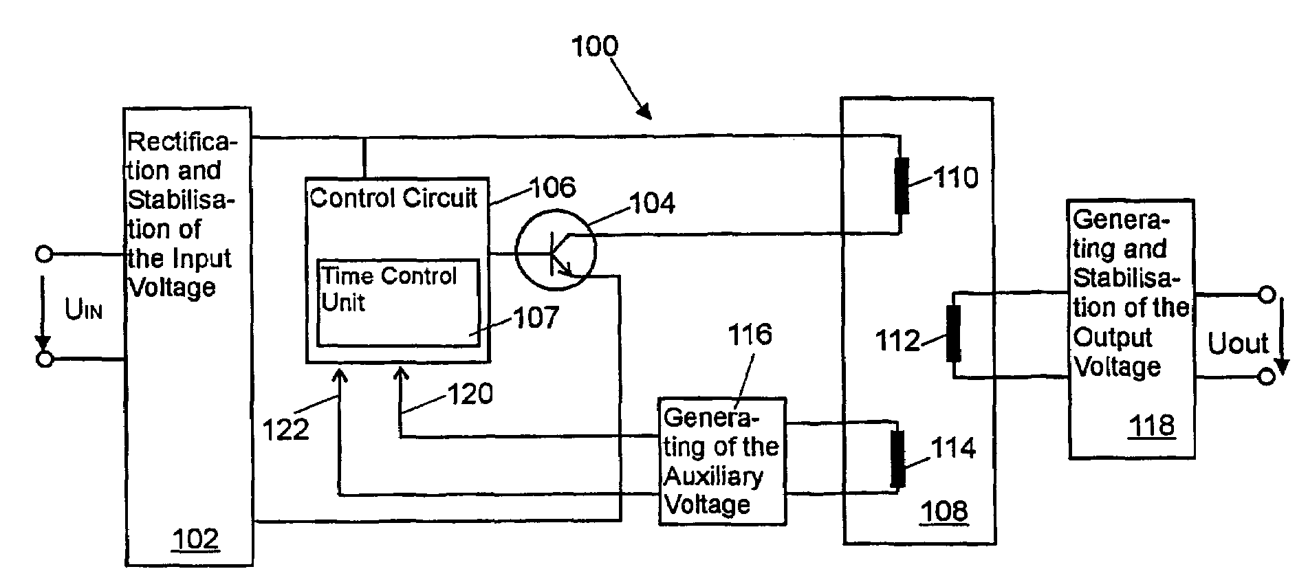
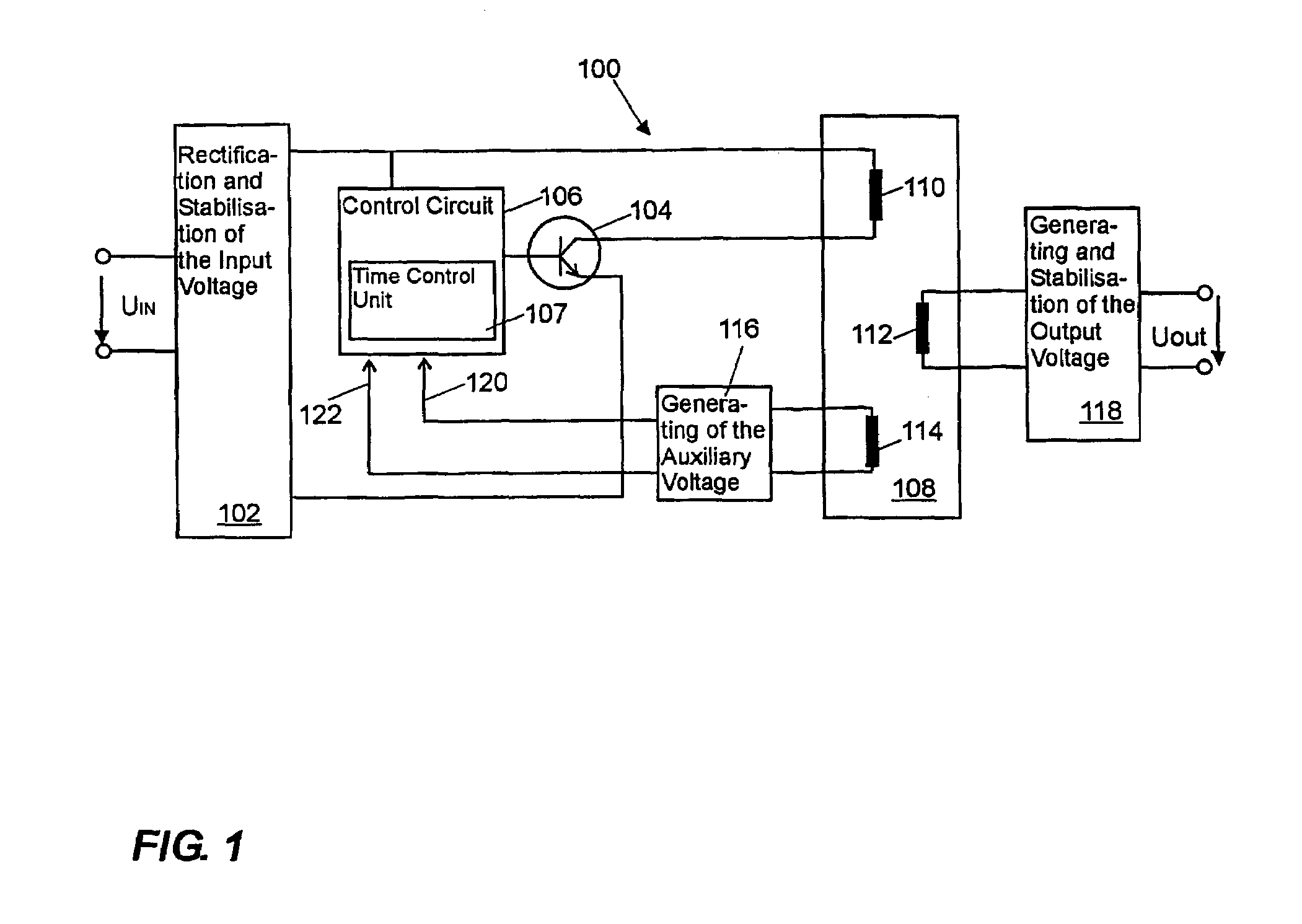
[0021]Referring now to the drawings and in particular to FIG. 1, a schematic block diagram of a switched-mode power supply according to this invention is shown. The alternating voltage UIN, which may for example be the mains voltage, is applied to the input of the switched-mode power supply 100. In Europe the mains voltage varies between 180 V and 264 V alternating voltage and in America between 90 V and 130 alternating voltage. The input voltage is rectified and stabilised in block 102. In addition, it is ensured that interference signals, which are generated in the switched-mode power supply, do not access the alternating voltage network. The primary-side winding 110 of the isolating transformer 108 and the primary-side switch 104, which is a transistor here, form a series circuit, which is c...


PUM


Abstract

This invention relates to a primary-controlled switched-mode power supply of the type of a free-running flyback converter, which comprises a transformer with a primary-side winding, a secondary-side winding and at least one auxiliary winding. The switched-mode power supply comprises a primary-side switch, which is connected to the primary-side winding, in order to interrupt a current flow through the primary-side winding, a freely oscillating circuit for the generation of switching pulses, which drive the primary-side switch, and a circuit for generating an image voltage between the terminals of the auxiliary winding, in order to generate an image voltage, which on the primary side forms a voltage to be regulated on the secondary side. In order to provide a switched-mode power supply of this type, which with reduced complexity enables an improved control characteristic and an increased flexibility with regard to the operating parameters, the switched-mode power supply further comprises a time control unit, which is coupled to the primary-side switch such that the duration of a turn-off period of the primary-side switch can be adjusted within a switching cycle.

Description

BACKGROUND OF THE INVENTION[0001]1. Field of the Invention[0002]This invention relates to a switched-mode power supply, in particular a switched-mode power supply with a primary side and a secondary side, which has a transformer with a primary-side winding, a secondary-side winding and at least one auxiliary winding. The primary-side winding and the auxiliary winding are connected to the primary side and the secondary-side winding is connected to the secondary side. The switched-mode power supply comprises a primary-side switch, which is connected to the primary-side winding, in order to interrupt a current flow through the primary-side winding, a freely oscillating circuit for the generation of switching pulses, which drive the primary-side switch, and a circuit for the generation of an image voltage between the terminals of the auxiliary winding, in order to generate an image voltage, which on the primary side forms a voltage to be regulated on the secondary side.[0003]2. Descript...

Claims


Application Information

Patent Timeline
Patent Type & Authority Patents(United States)
IPC IPC(8): H02M3/335H02M3/338
CPCH02M3/3385H02M3/33507
Inventor BERGHEGGER, RALF SCHRODER GENANNT
Owner POWER SYST TECH
Learn More