Camera head for fast reproduction of a vacuum UV spectrometer spectrum

a vacuum uv spectrometer and camera head technology, applied in the direction of optical radiation measurement, radiation particle tracking, luminescent dosimeters, etc., can solve the problem of insufficient gain, achieve the effect of increasing the efficiency of the complete system, increasing the height of the slit, and increasing the deterioration of the wavelength resolution

Inactive Publication Date: 2007-11-13
FORSCHUNGSZENTRUM JULICH GMBH
View PDF5 Cites 1 Cited by
  • Summary
  • Abstract
  • Description
  • Claims
  • Application Information

AI Technical Summary

Benefits of technology

[0026]The MCP surface is preferably coated with CsJ in order to increase efficiency (quantum yield).
[0027]For the series-connected phosphor screen for the conversion of the electron pulse into visible light, a special, very fast phosphor (Type P46) is chosen in particular, whose afterglow / decay time (some 10 μs) is noticeably less than the desired time resolution of the total system, and which, in addition, has a large light yield in the wavelength range in which the series-connected camera head has its highest degree of efficiency (approx. 500-700 nm). Due to this design, a large gain of the MCP of up to 105 can be achieved in total, at a high degree of efficiency, high time resolution and acceptable spatial resolution (minimum spot size at the output is approx. 60 μm).
[0029]Essentially, the spatial resolution of the MCP now also determines the optimum width for the entrance slit up to which the incident amount of light (and thus the efficiency of the complete system) can be increased, without a noticeable additional deterioration of the wavelength resolution occurring. Therefore, a width of 50 μm is preferably chosen.
[0030]If an additional increase of the incident amount of light is desired without a loss in resolution, the height of the slit is increased according to the invention. This necessitates (because of the 1:1 image in the spectrometer) a camera head for collecting the spectra whose sensor has as great a height as possible.

Problems solved by technology

As a rule, such a gain is insufficient.

Method used


Image

  • Camera head for fast reproduction of a vacuum UV spectrometer spectrum
  • Camera head for fast reproduction of a vacuum UV spectrometer spectrum
  • Camera head for fast reproduction of a vacuum UV spectrometer spectrum

Examples


Embodiment Construction

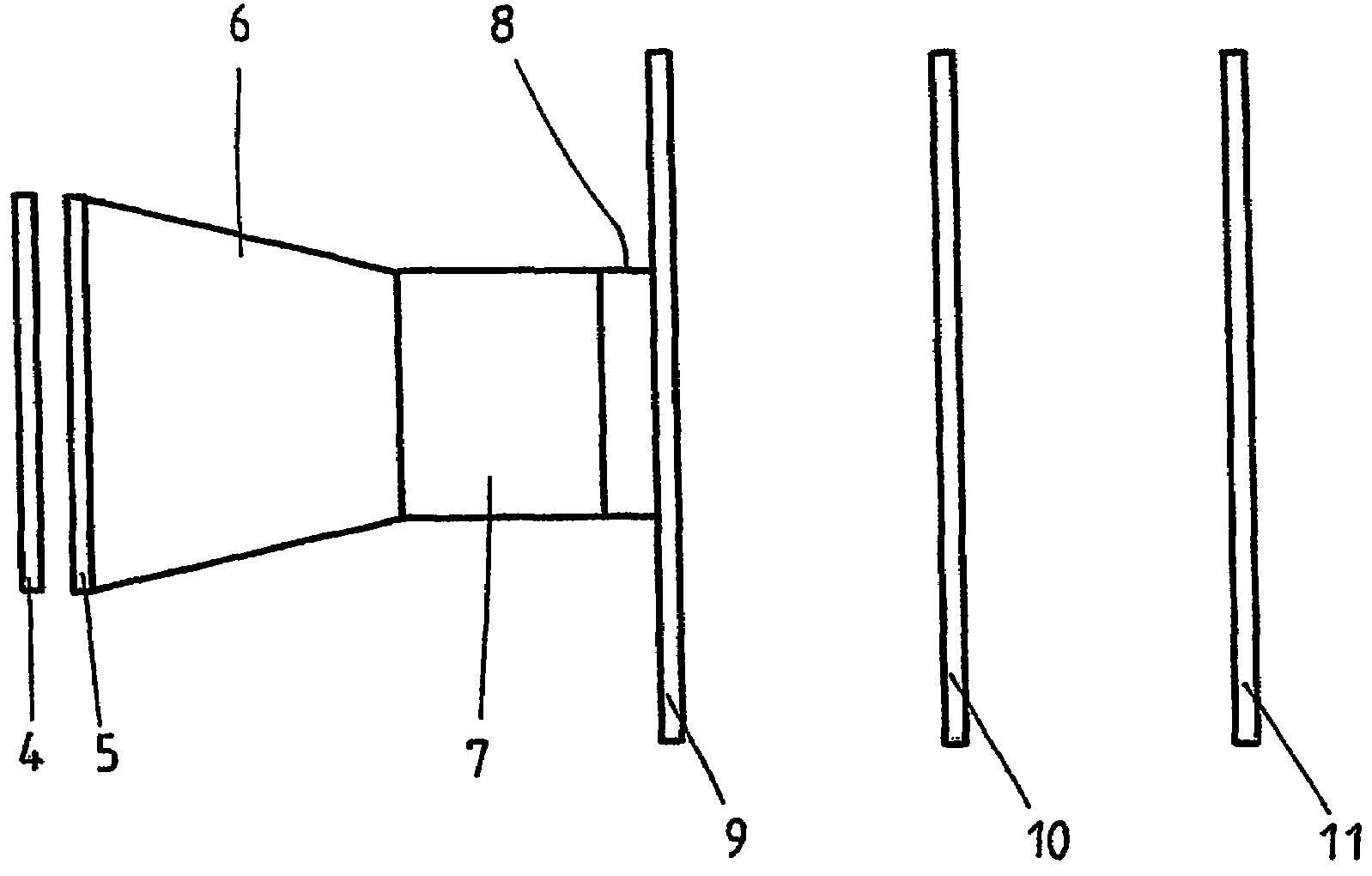
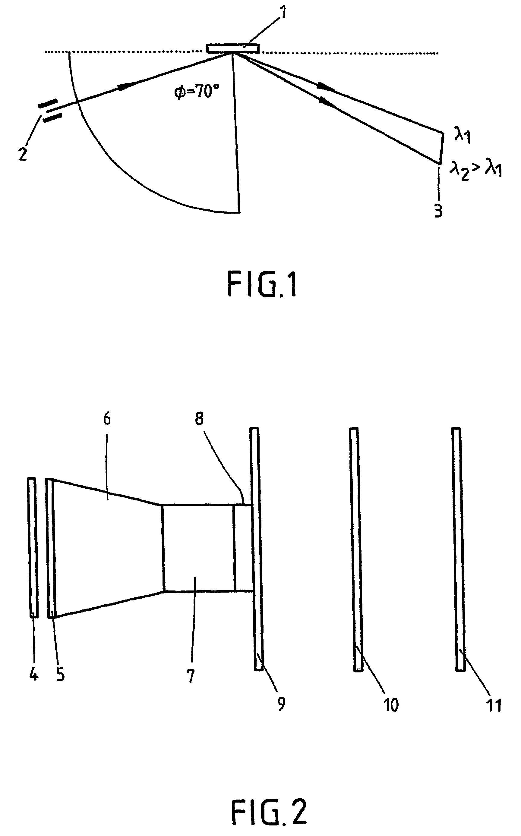
[0040]In one embodiment, a fiber optic cross-section converter (with a ratio of, for example 40 / 25) is mounted between the (phosphor) screen (width e.g. approx. 40 mm) and the sensor which makes the image (spectrum) smaller in the exemplary case. In this manner, an adjustment to the geometrical measurements of the sensor can be carried out. This fiber optic image is considerably more intense compared to an image created by means of lenses, and hence, is to be preferred for this application.

[0041]Since the permitted output intensity of the open MCP detector, modulated up to its linearity limit, does not suffice, as a rule, to modulate sensor S3904 (full capacity 25 pC) sufficiently, in a further embodiment, an image intensifier of the first generation (“diode”) with a fiber optic coupling is interposed between the fiber optic cross-section converter and sensor that can bring about an additional linear light intensification by a factor of 10-15 without significant losses in spatial re...


PUM


Abstract

An apparatus for measuring the transport time of impurity particles in a plasma includes a spectrometer, a system for the spatially-resolving conversion into charge of light exiting the spectrometer, an integrator circuit for the spatially-resolving integration of the charge, as well as a display screen that presents the integrated charge as a series of spectral lines. The integrator circuit is assembled from discrete components. Thus, the transport of plasma impurities can be properly measured.

Description

FIELD OF THE INVENTION[0001]The invention relates to an apparatus for measuring the transport time of impurity particles in a plasma, comprising a spectrometer and a line-scan camera. The spectrometer has an entrance slit. The spectral lines emitted by the impurity particles fall through the entrance slit. Then, the spectral lines fall onto a diffraction grating. Depending on wavelength, the spectral lines are reflected at different angles. The split light signals leaving the spectrometer are collected by a spatially-resolving line-scan camera. The transport time is calculated from the measurement information thus obtained. During operation, the spectrometer is located in a vacuum atmosphere.BACKGROUND OF THE INVENTION[0002]For the experimental examination of the radial transport of plasma impurities, i.a. a small amount of a plasma impurity is introduced into the plasma at the plasma edge, and then, the development in time of the spectral lines of different degrees of ionization is...

Claims


Application Information

Patent Timeline
Patent Type & Authority Patents(United States)
IPC IPC(8): G01T5/08G01J3/443G01J1/02G01J1/42G01J1/44G01J3/28G01J3/36
CPCG01J1/58G01J3/2889G01J3/2803
Inventor BIEL, WOLFGANGSCHOLL, ALFREDSANDRI, NORBERTTELEMANN, GERDBRINKMANN, DIETMAR
Owner FORSCHUNGSZENTRUM JULICH GMBH
Why Eureka
Try Eureka