
Bolt with function of measuring strain

a technology of bolts and functions, applied in the field of bolts, can solve the problems of inability to adapt to applications, constant monitoring of strain in many bolts, and serious problems in the accuracy of measured values, and achieve the effect of high accuracy

Active Publication Date: 2007-11-13
HITACHI LTD
View PDF29 Cites 41 Cited by
  • Summary
  • Abstract
  • Description
  • Claims
  • Application Information

AI Technical Summary

Benefits of technology

Enables accurate and long-term strain measurement without battery consumption, maintaining high accuracy even with temperature distributions, and preventing noise interference in the measurement circuit.

Problems solved by technology

Since a fiber cable and a lead wire must be taken outside from a head of a bolt in these technologies to become an obstacle at the time of bolt clamping, however, the technologies are not suited to applications, in which strain in many bolts is monitored constantly.
Therefore, a serious problem comes out in accuracy of measured values in the case where temperature distribution is involved in a bolt as frequently experienced in clamp bolts of a piping system.
However, there is caused a problem that a sensor is limited in service life because of being battery-operated.
Since ordinary strain sensors consume a battery due to flow of electric current of a current value in the order of mA, the number of measurements of an amount of strain is limited.

Method used


Image

  • Bolt with function of measuring strain
  • Bolt with function of measuring strain
  • Bolt with function of measuring strain

Examples


Embodiment Construction

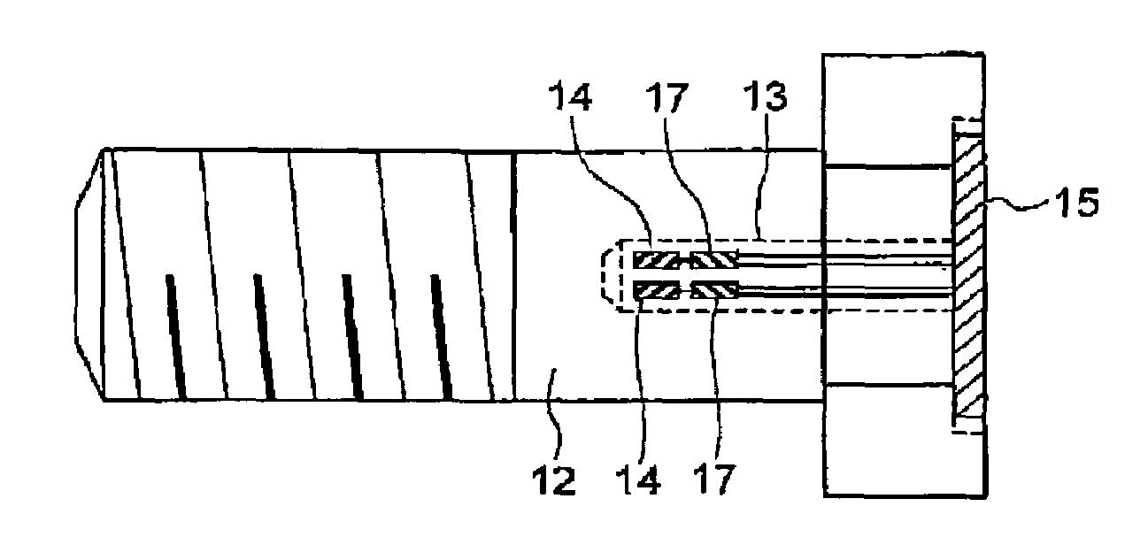
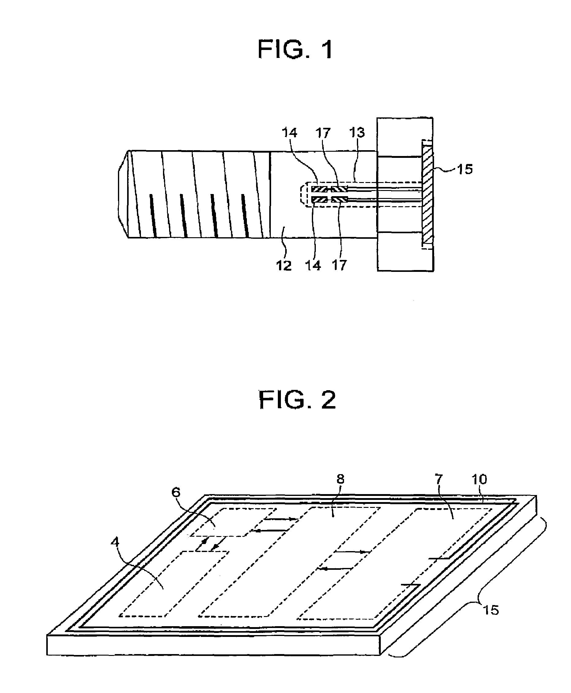
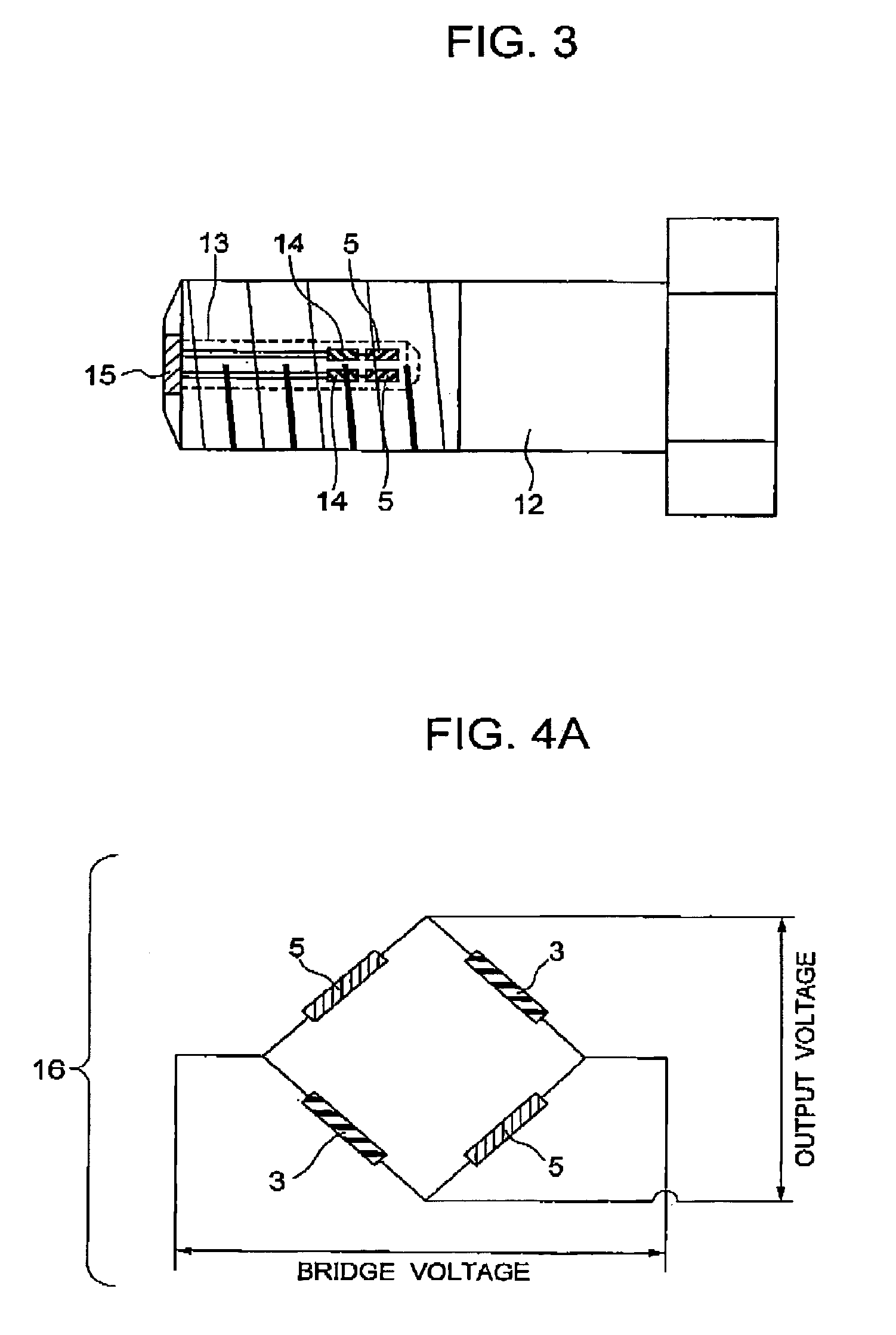
[0056]A first embodiment of the invention will be described hereinafter with reference to FIGS. 1 to 6. FIG. 1 shows a bolt 1 with a function of measuring strain, according to a first embodiment of the invention. The embodiment is the bolt 1 with a function of measuring strain characterized in that a wire resistance type or polysilicon strain gauges 14 and dummy resistors 5 are mounted in a hole 13 provided in an axial direction of a bolt 12, and in addition thereto, a chip 15 is provided in which a group of strain sensor amplifiers 4, an analog / digital converter 6, a rectification•detection•modem circuit 7, a communication control 8, and an antenna 10 are accommodated. As shown in FIG. 2, the group of strain sensor amplifiers 4, the analog / digital converter 6, the rectification•detection•modem circuit 7, and the communication control 8 are formed on the common chip 15 made of a monocrystal silicon and the chip 15 is arranged in the vicinity of a surface of a head of the bolt 12. In...


PUM

PropertyMeasurementUnit
mechanical quantityaaaaaaaaaa
temperatureaaaaaaaaaa
temperature distributionaaaaaaaaaa

Abstract

A bolt with a function of measuring strain, comprising a Wheatstone bridge circuit comprising a strain sensor and a dummy resistor, a translate circuit that amplifies a signal from the Wheatstone bridge circuit to convert the same into a digital signal, a transmitting circuit that transmits the digital signal outside the bolt, and a power circuit, by which electromagnetic wave energy received from outside the bolt is supplied as a power source for at least any one of the circuits.

Description

BACKGROUND OF THE INVENTION[0001]The present invention relates to a bolt capable of measuring a mechanical quantity.[0002]As a technology that monitors strain of a bolt, method, in which a slot is provided in an axial direction (lengthwise) of a bolt and optical fibers are inserted into the slot to measure strain, and method of embedding a strain gauge into the slot, have been put into practical use. Since a fiber cable and a lead wire must be taken outside from a head of a bolt in these technologies to become an obstacle at the time of bolt clamping, however, the technologies are not suited to applications, in which strain in many bolts is monitored constantly. Hereupon, it is thought of, as a solution, to embed a strain sensor, such as strain gauge, etc., in a bolt and to take out measured values through display or radio waves. JP-A-11-118637 is listed as a patent therefor, and shows a sensor bolt comprising a sensor, an amplifier for sensed values, and a battery built in the bolt...

Claims


Application Information

Patent Timeline
Patent Type & Authority Patents(United States)
IPC IPC(8): G01B7/16G01L1/00
CPCF16B31/02G01L5/24G01L5/0004G01B7/18
Inventor OHTA, HIROYUKISUMIGAWA, TAKASHI
Owner HITACHI LTD
Learn More