Tapered roller bearing and final reduction gear

a technology of tapered roller bearing and final reduction gear, which is applied in the direction of gearing details, mechanical equipment, gearing, etc., can solve the problems of reducing torque, affecting the reduction of torque, so as to prevent the early seizure and separation of the inner race, the effect of reducing the torque loss

Inactive Publication Date: 2007-10-16
JTEKT CORP
View PDF19 Cites 0 Cited by
  • Summary
  • Abstract
  • Description
  • Claims
  • Application Information

AI Technical Summary

Benefits of technology

[0011]An object of the present invention is to provide, a tapered roller bearing capable of solving these problems, preventing the early seizure and separation thereof, and reducing a torque loss.
[0012]Another object of the present invention is to provide a final reduction gear which enables the fuel consumption to be improved by using highly rigid tapered roller bearings, and which has made improvements concerning a decrease in the lifetime and an increase in the manufacturing cost thereof.

Problems solved by technology

However, as compared with a ball bearing, a torque loss in slide contact portions of a larger end surface of the tapered roller and a larger collar (rib) surface of the inner race both of which exert an axial load on each other is large.
Therefore, the reduction of torque becomes a problem from the viewpoint of the saving of energy.
As a result, the function of the bearing is not displayed sufficiently.
Moreover, the regulation of a pre-load and a clearance is difficult.
The roller bearings in the differential gear unit have heretofore been made of tapered roller bearings so as to obtain a high rigidity thereof but the reduction of the torque of the bearings has become a problem from the viewpoint of improving the fuel consumption.
Therefore, new problems arise which include an increase in the manufacturing cost occurring due to a change in materials and the like made so that low torque loss and a high rigidity of the differential gear unit stand together, and a fear of a decrease in the lifetime of the differential gear unit which will be caused by the use of the gear unit in an extraneous oil.
The final gear unit also has a problem of reducing the torque loss of the tapered roller bearings for the same reasons mentioned above.

Method used


Image

  • Tapered roller bearing and final reduction gear
  • Tapered roller bearing and final reduction gear
  • Tapered roller bearing and final reduction gear

Examples


first embodiment

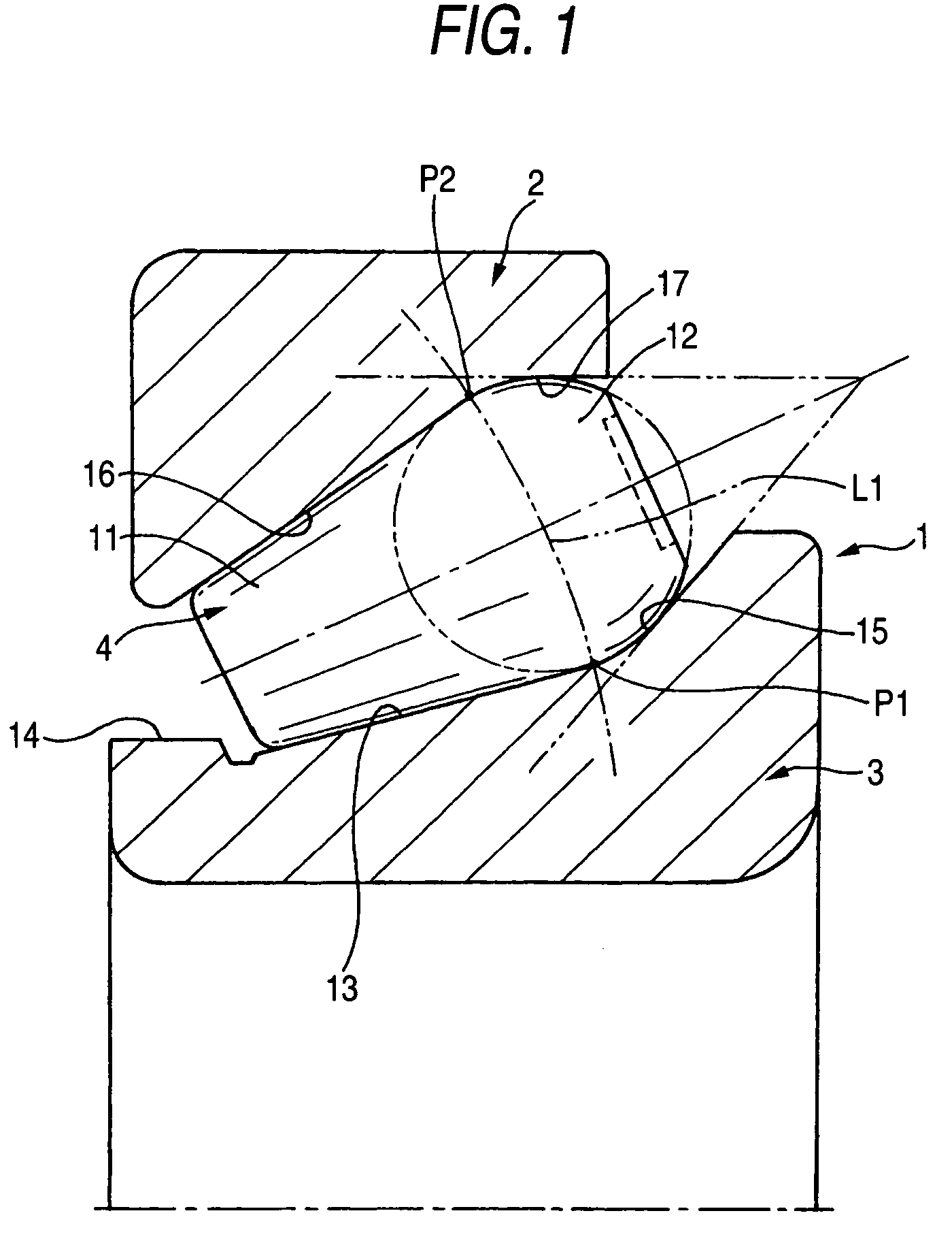
[0046]A tapered roller bearing 1 according to the present invention shown in FIG. 1 includes an outer race 2, an inner race 3, and a plurality of tapered rollers 4 arranged between these races.

[0047]Each tapered roller 4 includes a tapered body 11, and a larger end surface 12 provided at a right end portion thereof. The larger end surface 12 of the tapered roller 4 is formed as a convex curved surface connected to the tapered surface of the body 11 at an intersection of the larger end surface 12 and a curve L1 shown by a two-dot chain line. In the first embodiment, this curved surface is formed convexly.

[0048]The inner race 3 includes a tapered raceway surface 13, a smaller collar surface 14 provided at a left end portion of the raceway surface 13, and a larger collar rib surface 15 provided at a right end portion of the raceway surface 13. The larger collar rib surface 15 is formed as a concave curved surface opposed to the convex curved surface region of the larger end surface 12 ...

second embodiment

[0051]FIG. 3 shows the tapered roller bearing 1 according to a second embodiment of the present invention. In an inner race 3, an annular groove (recess) 18 for preventing the interference of the parts with each other during the manufacturing thereof is formed between the tapered raceway surface 13 and a concave larger end surface 15. The construction of the other portions of the bearing is identical with that of the corresponding portions of the first embodiment shown in FIG. 1. Therefore, the same reference numerals will be added to such portions, and the description thereof will be omitted.

[0052]According to the tapered roller bearing 1 shown in FIG. 3, the outer race 2 and the inner race 3 are in linear contact with the tapered roller 4 so that these parts have stress distribution shown by hatches of broken lines in the same drawing. Owing to the annular groove 18 formed in the inner race 3, the stress in the mentioned portion thereof becomes zero but the general stress distribu...

third embodiment

[0054]A tapered roller bearing 41 according to a third embodiment shown in FIG. 4 includes an outer race 42, an inner race 43, a plurality of tapered rollers 44 arranged between these races, and a retainer 45 for retaining the tapered roller 44.

[0055]The tapered roller 44 includes a tapered body 51, and a larger end surface 52 provided on a right end portion thereof. The larger end surface 52 of the tapered roller 44 is formed by a convex curved surface continuing to a tapered surface of the body 51. In the third embodiment, this curved surface is a convex spherical surface.

[0056]The inner race 43 includes a tapered raceway surface 53, a smaller collar surface 54 provided at a left end portion of the raceway surface 53, and a larger collar rib surface 55 provided at a right end portion of the raceway surface 53. The larger collar rib surface 55 is formed to a concave curved surface opposed to the convex curved surface out of the larger end surface 52 of the tapered roller 44. In the...


PUM


Abstract

A tapered roller bearing includes: an outer race including an outer raceway surface; an inner race including an inner raceway surface and a larger collar surface which is a concave curved surface; and tapered rollers provided between the outer and inner races, each of the tapered rollers including a tapered surface and a larger end surface which is a convex curved surface communicating with the tapered surface and corresponds to the larger collar surface.

Description

BACKGROUND OF THE INVENTION[0001]This invention relates to a tapered roller bearing, and more particularly to a tapered roller bearing in which a torque loss is reduced and further relates to a final reduction gear adapted to transmit driving torque from a driving power source, such as an engine to an axle, and more particularly to a final reduction gear in which a roller bearing has been improved.[0002]A tapered roller bearing having an outer race, an inner race and a plurality of tapered rollers arranged between these races is compact, and capable of supporting a large radial load and an axial load and, moreover, being used at a high rotational speed. However, as compared with a ball bearing, a torque loss in slide contact portions of a larger end surface of the tapered roller and a larger collar (rib) surface of the inner race both of which exert an axial load on each other is large. Therefore, the reduction of torque becomes a problem from the viewpoint of the saving of energy.[...

Claims


Application Information

Patent Timeline
Patent Type & Authority Patents(United States)
IPC IPC(8): F16C33/36F16C19/36F16H1/14F16H48/08F16H48/42F16H57/02F16H57/021F16H57/037
CPCF16C19/225F16C19/36F16C33/36F16H57/037F16C2361/61F16H57/021F16H2048/423F16H48/08F16C19/364
Inventor UENO, HIROSHITODA, KAZUTOSHIDODORO, HIROFUMIKAMAMOTO, SHIGEOMATSUYAMA, HIROKILOU, LIMINGUEDA, MICHIRUOGINO, KIYOSHIHARUTA, TOMOHIROMATSUDA, SHINYAARAKI, NAOTOYAMAKAWA, KOSHIROKAJIHARA, KAZUHISATATEISHI, YOSHIO
Owner JTEKT CORP
Why Eureka
Try Eureka