Medical irradiation apparatus

a technology of irradiation apparatus and irradiation chamber, which is applied in the field of medical irradiation apparatus, can solve the problems of insufficient cooling effect, insufficient sight of effective, and insufficient improvement, and achieve the effect of efficient restraint of heat generation and high power

Inactive Publication Date: 2007-10-02
MORITA MFG CO LTD
View PDF8 Cites 23 Cited by
  • Summary
  • Abstract
  • Description
  • Claims
  • Application Information

AI Technical Summary

Benefits of technology

[0010]The present invention is proposed in order to solve the above-mentioned problems and provides a new medical irradiation apparatus capable of high power and downsizing in which an irradiation light is advantageously used for a desired purpose and heat generation is efficiently restrained.
[0011]The first object of the present invention is to effectively utilize the outgoing light in a treatment target area by setting the shape of an annular reflective member and a lens member in such a manner that almost all the outgoing light from the lens member is emitted to a specified irradiation area, thereby executing an objective treatment effectively and accurately. Further, the light diverging laterally from the light emitting element constituting the luminous body is reflected forward by the annular reflective member, so that the reflection light is also directed to irradiate on the area to be reflected, thereby effectively utilizing the luminous ability of the light emitting element. Therefore, high power is obtained without arranging many light emitting elements and downsizing is achieved. In addition, the luminous body is protected with the lens member, thereby preventing contamination and damage.
[0012]The above-mentioned specified area is formed substantially cylindrical around the optical axis of the outgoing light, the distribution of the illumination intensity in the field area in each irradiation field orthogonal to the optical axis in the irradiation area is substantially uniform, and the illumination intensity in any irradiation fields is almost the same. In case of hardening the prosthetic photo polymerization resin in the tooth, homogenous and rapid hardening is carried out by positioning the tooth surface in the specified area. Accordingly, the combination of the shape of the annular reflective member and the shape of the lens member makes possible that the distribution of the illumination intensity in each irradiation field in a specified area is made substantially uniform and the illumination intensity in each irradiation filed is made substantially the same.

Problems solved by technology

Therefore, those inventions are not enough in the sight of effectively and homogenously hardening resin and a drastic improvement is required.
Therefore, its practical use has been highly evaluated, however, the following problems have been pointed out.
Accordingly its cooling effect has not bee enough.
Specifically, because the light condensing means and the light introduction means which are provided at the front of the light emitting element often contact with gum, there causes an obstacle for medical treatment if heat generation of these means is restrained enough.

Method used


Image

  • Medical irradiation apparatus
  • Medical irradiation apparatus
  • Medical irradiation apparatus

Examples


Embodiment Construction

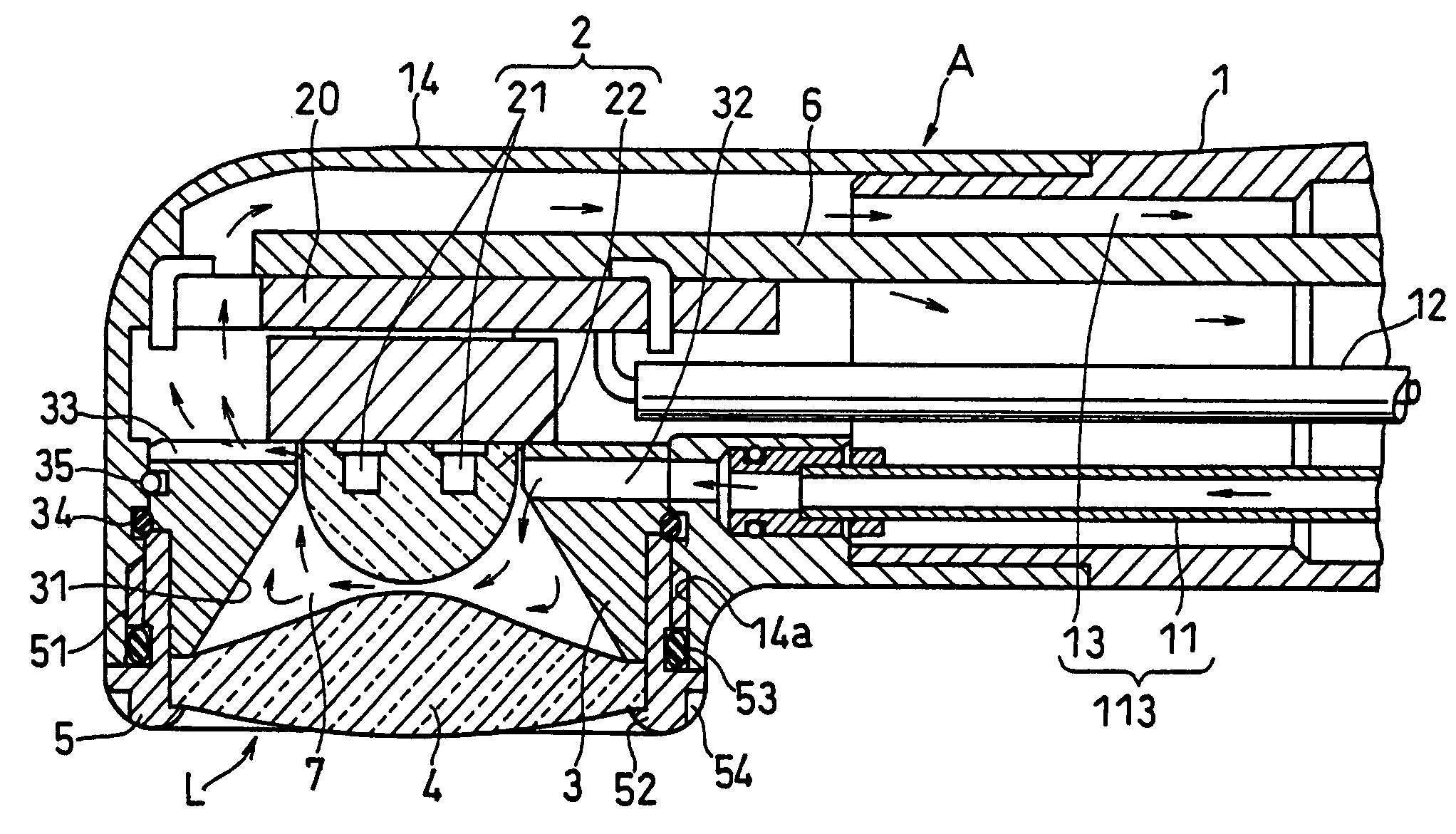
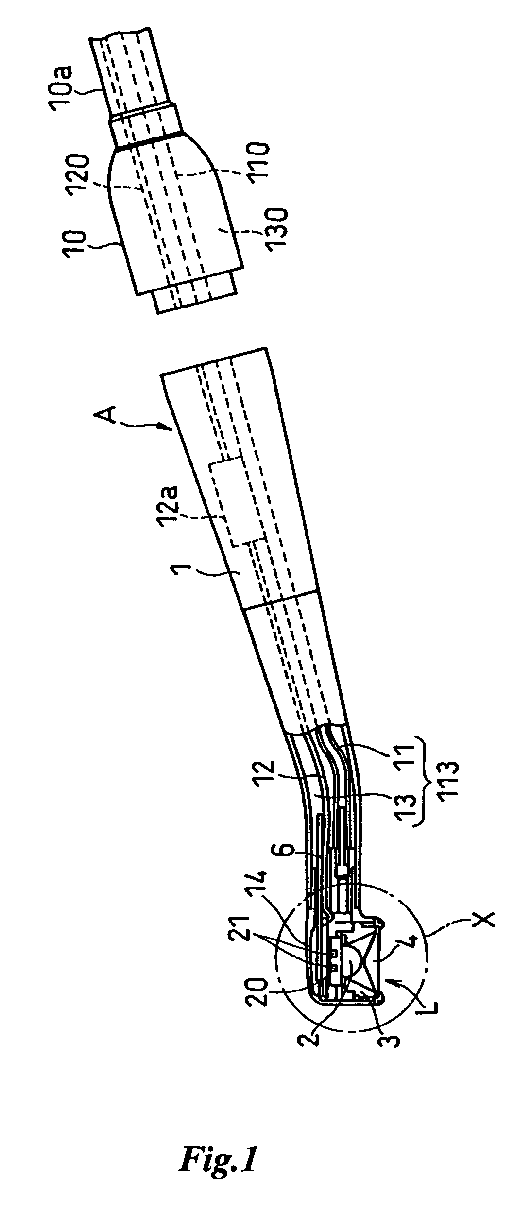
[0044]FIG. 1 and FIG. 2 show an embodiment in which the medical irradiation apparatus of the present invention is applied to a handpiece type dental photo polymerization apparatus A. The reference numeral 1 is a handpiece body (main body of irradiation apparatus) and is detachable to a base portion 10. A hose 10a housing a supply pipe 110 of compression air, a power cord 120, and an exhaust pipe 130 is connected to the base portion 10. The exhaust pipe 130 is defined by the space other than the supply pipe 110 and the power cord 120 in the hose 10a. The supply pipe 110 for compression air is connected to a compressor as an air supply means, not shown, provided in a dental treatment room and the power cord 120 is connected to a power source.

[0045]The base portion 10 of the handpiece constitutes a coupling to the handpiece body 1 such that when the base portion 10 is connected to the base end of the handpiece 1, the supply pipe 110 of compression air, the power cord 120 and the exhaus...


PUM


Abstract

A medical irradiation apparatus comprising a main body, a luminous body comprised of a light emitting element provided in a light outlet of the main body, an annular reflective member with a reflective surface provided at the circumference of the luminous body, the reflective surface reflecting the light from the luminous body forward, and a lens member provided so as to cover a forward opening of the reflective member, the lens member refracting and transmitting the direct light from the luminous body and the light reflected from the reflective member. According to the apparatus, all the outgoing light from the lens member is emitted so as to direct into a specified irradiation area.

Description

BACKGROUND OF THE INVENTION[0001]1. Field of the Invention[0002]The present invention relates to a medical irradiation apparatus and more particularly to improvement of a medical lighting installation such as a hardening apparatus of prosthetic photo polymerization resin, an intraoral lighting installation and the like in the dental treatment field.[0003]2. Prior Art[0004]In dental treatment, there used are a photo polymerization device for rapidly hardening the prosthetic photo polymerization resin in a tooth, an irradiation device, being attached to several kinds of handpieces or individually, for irradiating an objective tooth for treatment in the oral cavity, a dental light (shadowless light) standing at the side of a treatment bed for irradiating the oral cavity, and the like. Such a light is required to condense the light in a narrow oral cavity and is different from the light used in other fields which is required to illuminate wide area.[0005]Halogen lamp and a xenon lamp ha...

Claims


Application Information

Patent Timeline
Patent Type & Authority Patents(United States)
IPC IPC(8): A61C3/00A61N5/06A61C13/38A61C13/15
CPCA61C19/004A61C13/00
Inventor KATSUDA, NAOKIOGAWA, HARUOMATOBA, KAZUNARI
Owner MORITA MFG CO LTD
Why Eureka
Try Eureka