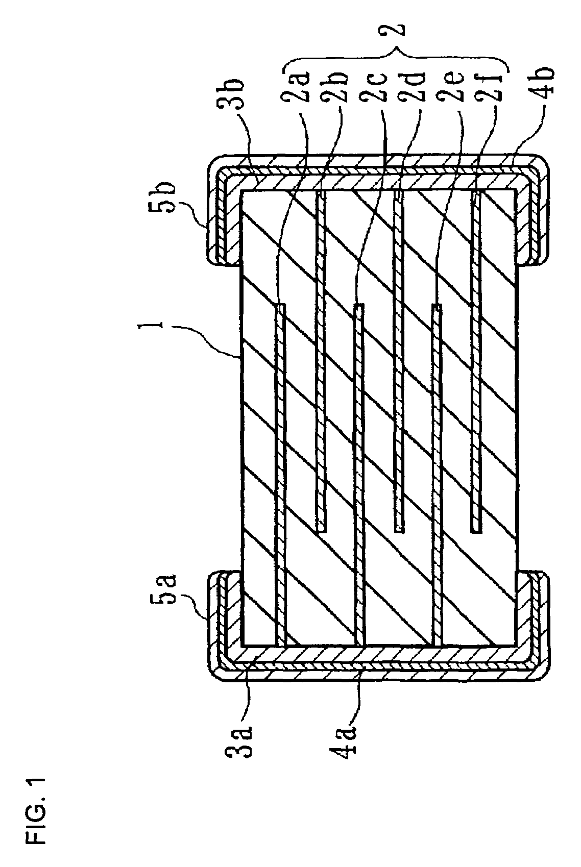
Dielectric ceramic and monolithic ceramic capacitor
a monolithic ceramic and dielectric ceramic technology, applied in the direction of ceramics, fixed capacitors, electrical equipment, etc., can solve the problems of reducing reliability, affecting the reliability of the capacitor, and reducing the relative dielectric constant, so as to improve the reliability, improve the dielectric strength, and improve the high-temperature load life. , the effect of high reliability
- Summary
- Abstract
- Description
- Claims
- Application Information
AI Technical Summary
Benefits of technology
Problems solved by technology
Method used
Image
Examples
example 1
[0125]BaCO3, SrCO3, CaCO3, TiO2 and ZrO2 were prepared as ceramic raw materials and were weighed so that the main components had compositions shown in Tables 1 and 2. Each of the weighed raw material mixtures was placed in a ball mill containing PSZ and was wet mixed and pulverized for 24 hours. Then, the mixture was heated at a temperature of 1100 to 1180° C. to obtain a main component (Ba1-x-ySrxCay)m(Ti1-zZrz)O3.
[0126]In this Example, the Sr component and the Zr component were purposely added to the main component in order to evaluate influences of a Sr component and a Zr component contained in (Ba,Ca)TiO3.
[0127]Then, each of the main component raw material powders was subjected to image analysis using a scanning electron microscope (SEM) to measure particle sizes of 300 particles of each powder. The average particle sizes were 0.2 to 0.5 μm as shown in Tables 1 and 2.
[0128]Then, BaCO3, MgCO3, MnCO3, CuO, V2O5 and SiO2 were prepared as additive component materials. Further, La2O3...
example 2
[0173]Li2O, B2O3, CaO, Al2O3, MgO, BaO, K2O, BeO, SrO, GaO, TiO2, and ZrO2 were prepared. Monolithic ceramic capacitors according to Examples 41 to 52 were fabricated so that the composition of each of the monolithic ceramic capacitors was the same as that of Example 3, as a standard sample, in [EXAMPLE 1] with the exception of the SiO2 site. The SiO2 site was adjusted so as to have the component composition shown in Table 5.
[0174]Table 5 shows sintering additives, molar amounts thereof, average grain sizes after sintering, and sintering temperatures in Example 3 and Examples 41 to 52.
[0175]
TABLE 5gXuOvXg3Si1.20.35120041Si / Li1.70.401080(1.19 / 0.51)42Si / B0.90.351120(0.6 / 0.3)43Si / Ca / Al0.70.301140(0.42 / 0.14 / 0.14)44Si / Li / Ca1.50.351100(1.35 / 0.075 / 0.075)45Si / B / Mg1.80.401080(1.26 / 0.36 / 0.18)46Si / Mg / Ba0.50.301150(0.35 / 0.05 / 0.1)47Si / B / K1.00.351140(0.8 / 0.15 / 0.05)48Si / Be / Sr1.40.451120(0.84 / 0.28 / 0.28)49Si / Li / B0.80.251140(0.56 / 0.16 / 0.08)50Si / Ti / Ga0.30.251150(0.16 / 0.09 / 0.05)51Si / Li / Na2.00.451040(1....
example 3
[0181]Next, monolithic ceramic capacitors according to Examples 61 to 70 were fabricated similar to [EXAMPLE 2] by the same method and process as those in Example 3 in [EXAMPLE 1], as a standard sample, except that predetermined impurities were added at predetermined molar amounts per 100 moles of the main component as shown in Table 7.
[0182]Table 7 shows the impurity components in Examples 61 to 70 and Example 3.
[0183]
TABLE 73——0.3561Zr / Ni / Fe0.530.35(0.5 / 0.02 / 0.01)62Zr / Ni / Co / Al0.070.35(0.04 / 0.01 / 0.01 / 0.01)63Zr / Ag / Mo0.080.30(0.05 / 0.02 / 0.01)64Zr / Fe / Ta0.320.40(0.3 / 0.01 / 0.01)65Zr / Pd / Zn0.080.30(0.04 / 0.02 / 0.02)66Zr / Hf / Fe0.440.35(0.4 / 0.02 / 0.02)67Ni / Nb0.320.35(0.3 / 0.02)68Zr / W0.060.35(0.05 / 0.01)69Ni / Cr / Mo0.520.40(0.5 / 0.01 / 0.01)70Zr / Cu / Ag0.430.35(0.4 / 0.02 / 0.01)
[0184]As is obvious from Table 7, also, it was confirmed that the average grain sizes after sintering were advantageously 0.21 to 0.45 μm in Examples 61 to 70.
[0185]Then, the relative dielectric constant εr, dielectric loss tan δ, maxi...
PUM
| Property | Measurement | Unit |
|---|---|---|
| grain size | aaaaa | aaaaa |
| grain size | aaaaa | aaaaa |
| thickness | aaaaa | aaaaa |
Abstract
Description
Claims
Application Information
 - R&D
- Intellectual Property
- Life Sciences
- Materials
- Tech Scout
- Unparalleled Data Quality
- Higher Quality Content
- 60% Fewer Hallucinations
Browse by: Latest US Patents, China's latest patents, Technical Efficacy Thesaurus, Application Domain, Technology Topic, Popular Technical Reports.
© 2025 PatSnap. All rights reserved.Legal|Privacy policy|Modern Slavery Act Transparency Statement|Sitemap|About US| Contact US: help@patsnap.com

