Eureka AIR delivers breakthrough ideas for toughest innovation challenges, trusted by R&D personnel around the world.

Open intervertebral spacer

a spacer and open technology, applied in the field of open chambered intervertebral spacers, can solve the problems of affecting the function of the spine, so as to improve the osteogenic and fusion promoting features, and the biomechanical features are satisfied

Inactive Publication Date: 2007-09-25
FLORIDA TISSUE BANK UNIV OF +1
View PDF93 Cites 109 Cited by
  • Summary
  • Abstract
  • Description
  • Claims
  • Application Information

AI Technical Summary

Benefits of technology

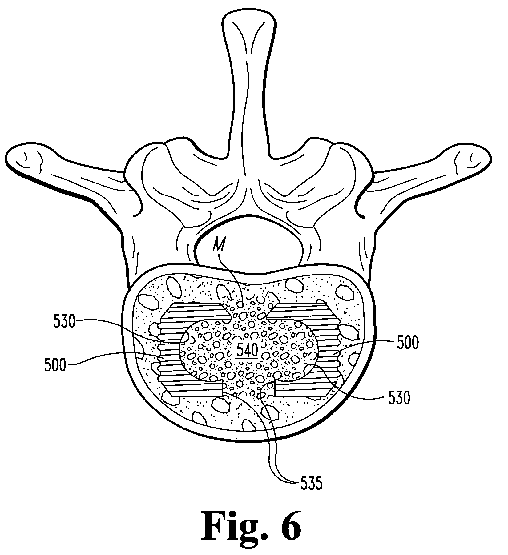
[0017]The combination of the open-chambered spacers of this invention with the tools and methods of this invention provide a versatile spacer without any compromise in biomechanical integrity. The spacers can be packed before or after implantation. This invention facilitates implanting a pair of open spacers close to each other in an intervertebral space. Where the spacer is a bone dowel, the dowel can be formed with less bone than is needed for conventional dowels, conserving precious bone stock.
[0019]Another object is to improve patient incidence of safe and satisfactory spinal stabilization and fusion.
[0021]Still another object of the present invention is to provide a spacer with satisfactory biomechanical features and improved osteogenic and fusion promoting features.

Problems solved by technology

Spinal discs may be displaced or damaged due to trauma, disease or aging.
The extruded nucleus pulposus may press on a spinal nerve, which may result in nerve damage, pain, numbness, muscle weakness and paralysis.
Intervertebral discs may also deteriorate due to the normal aging process or disease.
As a disc dehydrates and hardens, the disc space height will be reduced leading to instability of the spine, decreased mobility and pain.
Collapse of the disc space can cause instability of the spine, abnormal joint mechanics, premature development of arthritis or nerve damage, in addition to severe pain.
Moreover, the surgical procedures necessary to implant a rod or plate to stabilize the level during fusion were frequently lengthy and involved.
Success of the discectomy and fusion procedure requires the development of a contiguous growth of bone to create a solid mass because the implant may not withstand the compressive loads on the spine for the life of the patient.
Although the metal fusion devices of Sofamor Danek and others are widely and successfully employed for reliable fusions, it is sometimes desirable to use an all-bone product.
Although an all-bone spacer provides these and other benefits, the use of bone presents several challenges.
Cortical bone products may have sufficient compressive strength for such use, however, cortical bone will not promote rapid fusion.
While the bone dowels of the prior art are valuable bone grafting materials, these dowels have relatively poor biomechanical properties, in particular a low compressive strength.
Accordingly, these dowels may not be suitable as an intervertebral spacer without internal fixation due to the risk of collapsing prior to fusion under the intense cyclic loads of the spine.

Method used


Image

  • Open intervertebral spacer
  • Open intervertebral spacer
  • Open intervertebral spacer

Examples


example-1

Torsional Testing of “C”-Shaped Dowel

[0133]The C-shaped dowel of this invention was tested and the following measurements made of the dowel's ability to withstand insertional torque. The data presented here are for the 16 mm dowel. However, similar results are expected for other lengths of the dowel of this invention. For each dowel, a measured torque is applied to the dowel as it is maintained in a stationary position. For biological insertion of dowels, torques no higher than about 1 newton-meter are expected. The various dimensions measured in the following table correspond to the dimension shown in FIGS. 35-38:

[0134]

Diam.ODIDHeight% diff.(mm)(mm)(mm)(mm)Calc.Meas.-FailureFailureSampleD1W1W1*H**Thickness***Calc.TorqueType115.85.14.613.24.0154.00s. wall215.85.54.813.24.0193.5s. wall315.96.25.313.44.3253.89slot415.976.314.15.1234.95slot515.65.85.413.64.5215.2s. wall615.85.54.913.14.0244.36s. wall715.75.85.413.44.3274.00slotW1* = W1-T4;H** = see H1-H4, FIG. 16;calc. thickness*** = t...

example 2

Compression Testing

[0136]The “C”-shaped dowel of this invention was compressively tested and the load to failure was measured. It is anticipated that loads no higher than about 10,000 newtons are likely to be experienced in-place in the vertebral column. Compression testing of several different “C”-shaped dowels of this invention indicated that dowels of this invention survive axial compression loads significantly higher than the 15,000 newton threshold:

[0137]

AvgAvgAvgFailure#ThreadD1L1E2aE2bE2E1aE1bE1mass gLoad (N)1no15.925.55.34.75.03.94.44.24.19343722yes15.923.75.15.15.14.25.04.64.073135023no15.923.74.85.35.13.82.63.34.035137484yes15.922.57.17.07.17.05.46.25.075209405poor16.023.45.65.45.55.86.26.04.986224206yes15.726.17.17.17.18.48.68.55.331245007yes16.823.85.45.05.26.06.06.03.928143898yes17.622.44.85.55.25.84.65.25.448167309poor16.922.26.75.28.06.44.75.15.2261957610poor17.928.37.87.27.57.67.27.46.2012060611yes17.921.24.96.85.94.54.44.55.6542146112yes17.823.66.66.36.56.05.45.75.7...

example 3

Cervical Fusion Using “C”-Shaped Dowel

[0139]Preoperative Diagnosis. Ruptured cervical disc and spondylosis C5-6.

[0140]Operative Procedure. Anterior cervical discectomy and fusion C5-6.

[0141]After satisfactory general endotracheal anesthesia in the supine position, the patient is prepped and draped in the routine fusion. Incision is made in the skin length of the neck and carried through the platysma muscle. Dissection is carried down to expose the anterior vertebral column and the appropriate space identified by x-ray. Discectomy and foraminotomy are then performed and there is found a central, extruded fragment of disc toward the right side. When adequate decompression is achieved, a “C”-shaped dowel is cut from bone bank fibular and counter-sunk between the vertebral bodies to afford distraction. The wound is then irrigated with Bacitracin and closed in layers with Dexon and sterile strips.

[0142]Postoperative evaluation and subsequent patient monitoring reveals successful operativ...


PUM

PropertyMeasurementUnit
widthaaaaaaaaaa
widthaaaaaaaaaa
angleaaaaaaaaaa

Abstract

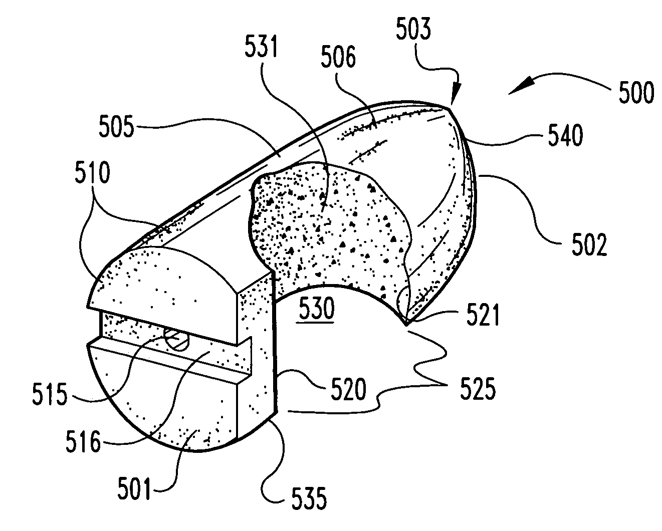
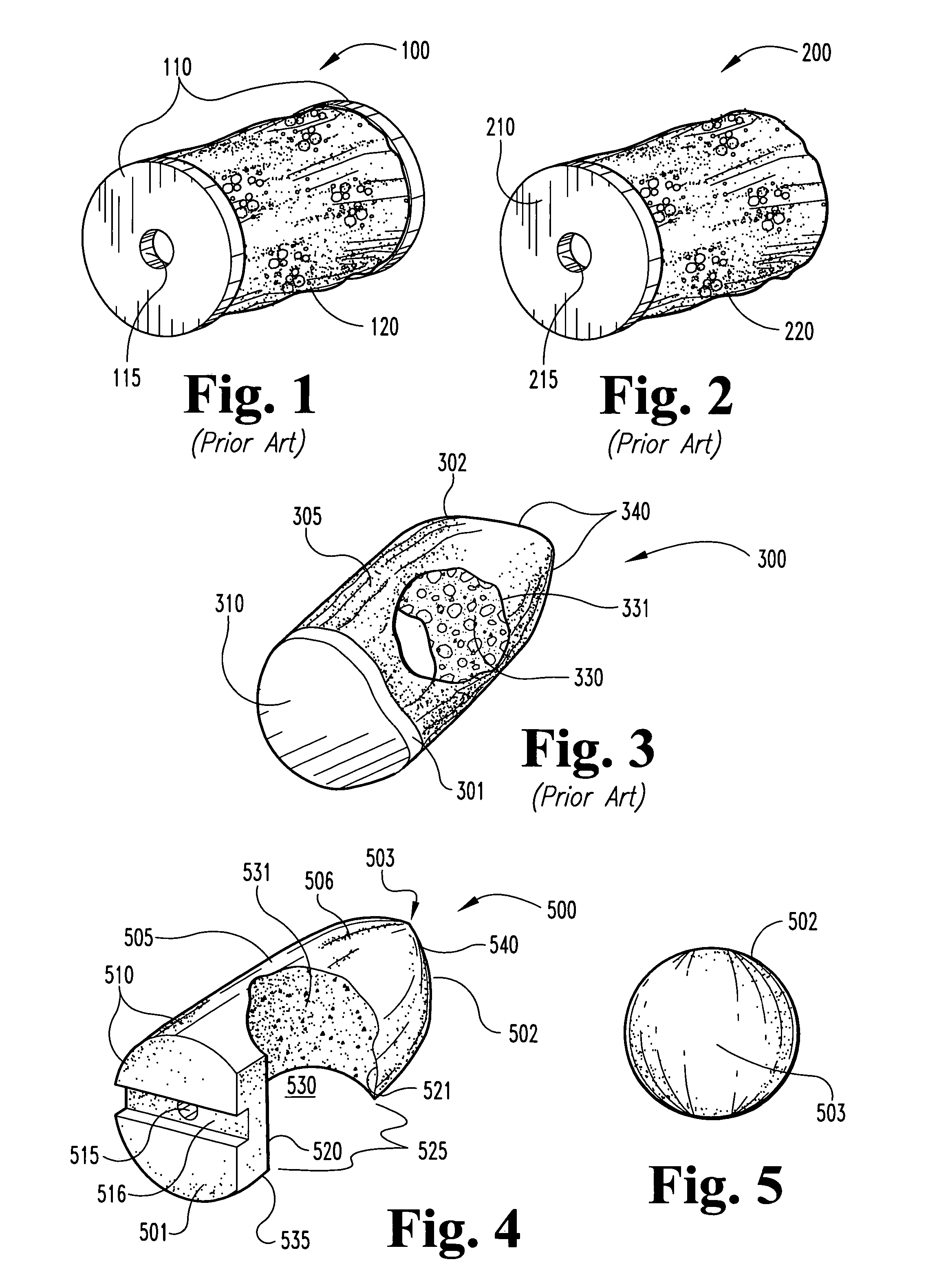
Open chambered spacers, implanting tools and methods are provided. The spacers 500′ include a body 505′ having a wall 506′ which defines a chamber 530′ and an opening 531′ in communication with the chamber 530′. In one embodiment the wall 506′ includes a pair of arms 520′, 521′ facing one another and forming a mouth 525′ to the chamber 530′. Preferably, one of the arms 520′ is truncated relative to the other, forming a channel 526. In one aspect the body 505′ is a bone dowel comprising an off-center plug from the diaphysis of a long bone. The tools 800 include spacer engaging means for engaging a spacer and occlusion means for blocking an opening defined in the spacer. In some embodiments, the occlusion means 820 includes a plate 821 extendable from the housing 805. In one specific embodiment the plate 821 defines a groove 822 which is disposed around a fastener 830 attached to the housing 805 so that the plate 821 is slideable relative to the housing 805.

Description

CROSS REFERENCE TO RELATED APPLICATIONS[0001]This application is a continuation of U.S. patent application Ser. No. 10 / 035,074, now U.S. Pat. No. 6,695,882. filed on Dec. 28, 2001, which is a continuation of U.S. patent application Ser. No. 09 / 453,787, now U.S. Pat. No. 6,409,765, filed on Dec. 3,1999, which is a divisional of U.S. patent application Ser. No. 08 / 867,963, now U.S. Pat. No. 6,033,438, filed on Jun. 3, 1997, all of which are incorporated herein by reference in their entirety.FIELD OF THE INVENTION[0002]The present invention broadly concerns arthrodesis for stabilizing the spine. More specifically, the invention provides open-chambered intervertebral spacers, instruments for implanting the spacers and methods for making and using the spacers.BACKGROUND OF THE INVENTION[0003]Intervertebral discs, located between the endplates of adjacent vertebrae, stabilize the spine, distribute forces between vertebrae and cushion vertebral bodies. A normal intervertebral disc includes...

Claims


Application Information

Patent Timeline
Patent Type & Authority Patents(United States)
IPC IPC(8): A61F2/44A61L27/00A61B17/16A61B17/88A61F2/00A61F2/02A61F2/28A61F2/30A61F2/46
CPCA61B17/1671A61F2/28A61F2/446A61F2/4601A61F2/4611A61F2/4644A61F2002/2835A61F2002/2839A61F2002/30057A61F2002/30062A61F2002/30131A61F2002/30143A61F2002/30224A61F2002/30596A61F2002/30616A61F2002/30617A61F2002/30772A61F2002/30795A61F2002/30797A61F2002/3082A61F2002/30871A61F2002/4475A61F2002/448A61F2002/4627A61F2002/4635A61F2002/4649A61F2210/0004A61F2230/0013A61F2230/0017A61F2230/0069A61F2250/0097A61F2310/00011A61F2310/00179A61B17/1604A61B17/8875A61F2/30724A61F2/3094A61F2/442A61F2/468A61F2002/2817Y10S623/908A61F2002/30594A61F2002/30593
Inventor BIANCHI, JOHN R.CARTER, KEVIN C.ESTES, BRADLEY T.BOYD, LARRYPAFFORD, JOHN A.
Owner FLORIDA TISSUE BANK UNIV OF
Why Eureka
Eureka Blog
Learn More