
Hand held antenna/network impedance analyzer

Inactive Publication Date: 2007-09-18
OHARRA II DALE G
View PDF6 Cites 17 Cited by
  • Summary
  • Abstract
  • Description
  • Claims
  • Application Information

AI Technical Summary

Benefits of technology

[0009]My advance in the art is an improved user interface and increased functionality in a small self-contained battery powered analyzer which most preferably includes a high contrast color display. Further, my unit includes the ability to measure and record in memory, measurement values for later use and display or download for further analysis and / or use by powerful computing equipment.
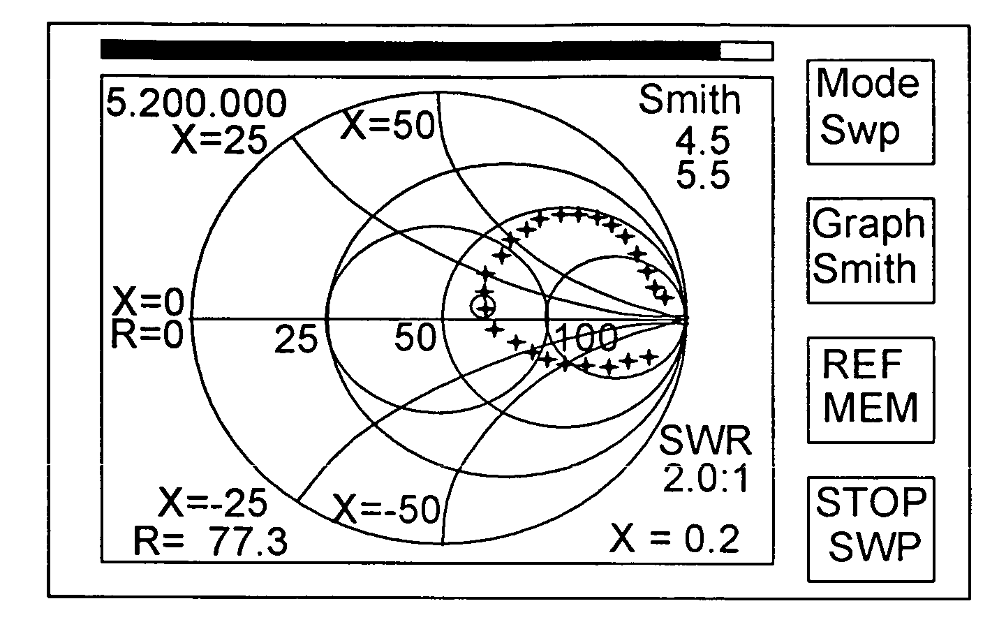
[0010]My analyzer employs a multi-mode control program and uses e.g. four software-defined user pushbuttons for control. Each pushbutton is physically aligned and associated with a visual display switch function box on the display screen which changes with changing function of the particular pushbutton. This arrangement provides a convenient, highly intuitive, and highly flexible human interface with all of the control values being provided by the user with a minimum number of pushbuttons. The function of each pushbutton is subject to change depending upon functional mode of the analyzer and is labeled in the associated visual indicator box on the display screen for user convenience. The rotary encoder can perform all frequency settings and memory location selection functions. A fifth pushbutton incorporated into the encoder shaft provides a convenient way to select digit positions of the frequency being adjusted by rotation of the encoder shaft, for example. Moreover, the complex (real and imaginary, or magnitude and phase) measurement data may be plotted in a variety of user-selectable display types to aid the user in visualizing and understanding the object or environment in which measurement is being made.
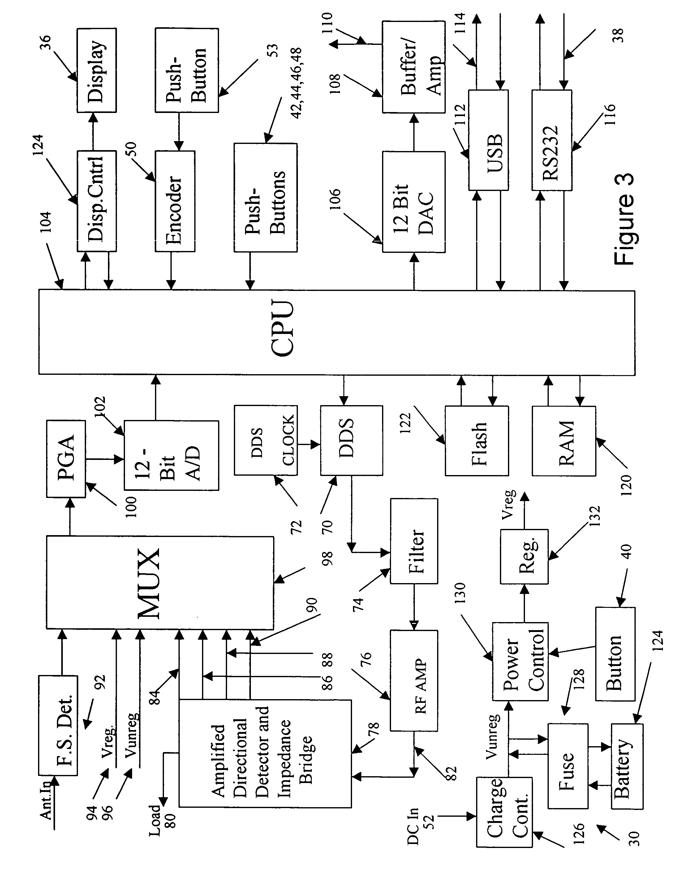
[0011]The functional and graphic display capabilities of my unit are directly a result of the design, layout and packaging of the unit, which forms an important aspect of the present invention, including use of a very powerful mixed analog / digital signal embedded microprocessor including considerable flash memory resources for reading and digitally quantizing measurement values and for driving an on-board direct digital synthesizer chip. The microprocessor directly controls a visual display process driving a transreflective color LCD display, and also provides at least one port to enable connection to an external computing resource. User inputs include a rotary quadrature encoder and a plurality of user push button switches. The software enables multiple functions to be carried out with the encoder and switches, based on software-defined functions selected by the user at the push button switches. Available functions are conveniently displayed to the user in proximity with the appropriate push button switches. This approach facilitates an efficiently small handheld package with considerable functionality with a minimum of controls and user inputs. A high-resolution calibration mode enables the user to calibrate the internal direct digital synthesis generator against a known frequency standard. A graphics setup mode enables the user to set a variety of available display parameters. For example, in one preferred embodiment the user may rapidly set a single cursor to a center frequency of interest in a current frequency sweep display. Once set, a push button enters a two-cursor mode that enables the user to adjust the sweep width as centered about the originally set cursor.
[0014]Another aspect of the design is the PCB layout of a two-layer printed circuit board that effectively separates the analog and digital processes, and that further enables the LCD module to be connected as a daughter board.

Problems solved by technology

In addition, such instruments have not included functionality to characterize and store feed line impedance (compare the Barker QEX article cited above where the technique described is very complex to carry out).
Also, such instruments have not included software-defined graphic user display capabilities for providing the measurement results in a plurality of user-selected formats, including real time Smith Chart, for example, (or Arndt Chart graphing real and complex Rho (complex voltage reflection coefficient, see Walter Maxwell, Reflections II, Transmission Lines and Antennas, WorldRadio Books, Sacramento, Calif., copyright 2001, Chapter 3).

Method used


Image

  • Hand held antenna/network impedance analyzer
  • Hand held antenna/network impedance analyzer
  • Hand held antenna/network impedance analyzer

Examples


Embodiment Construction

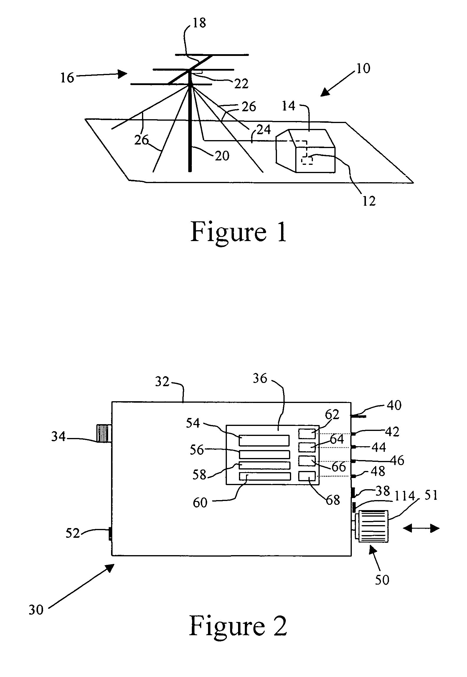
[0041]FIG. 1 illustrates in simplified view a radio transmitting installation 10 including transmitter apparatus 12 in a shelter 14, a multi-element Yagi or log periodic directional beam antenna 16 mounted to a beam 18 at the top of a tower 20. In the present example, the antenna is designed and intended to operate in the high frequency and low very high frequency bands, such as between 3.5 MHz and 54 MHz. While a horizontally polarized beam antenna array is illustrated, other antenna types, including dipoles, verticals, etc., may be measured and characterized by the antenna analyzer of the present invention.

[0042]The antenna 16 includes a feed point 22 to which is connected a transmission line 24 leading down the tower 20 an over to the transmitter apparatus 12. The tower 20 may be free standing or it may be stabilized in place by guy wires 26 as is well known in the art. In order to adjust properly the transmitter apparatus 12 for maximum power transfer to the antenna 16, the impe...


PUM


Abstract

A handheld portable battery powered digital antenna and / or network analyzer which derives complex impedance values at a given frequency includes an internal direct digital synthesis generator and provides software-defined multiple operating modes and real time graphic scalar and polar displays of results in a multiplicity of user-selectable visual formats.

Description

REFERENCE TO RELATED APPLICATION[0001]The benefit of U.S. Provisional patent application Ser. No. 60 / 657,276, filed on Mar. 1, 2005, and entitled “Hand Held Antenna / Impedance Analyzer” is hereby claimed, and the disclosure thereof is hereby expressly incorporated by reference.FIELD OF THE INVENTION[0002]The present invention relates to portable electronic test apparatus and methods. More particularly, the present invention relates to a handheld battery powered multi-mode digital antenna and / or network analyzer which directly derives complex impedance values at a given frequency controlled by an internal direct digital synthesis generator and provides software-defined multiple operating modes and real time graphic display of results in a multiplicity of user-selectable visual formats.BACKGROUND OF THE INVENTION [0003]A Wheatstone bridge implemented as a directional coupler is a well-known impedance measurement circuit. It is also known to implement an impedance measurement circuit as...

Claims


Application Information

Patent Timeline
IPC IPC(8): G01R23/00
CPCG01R27/04G01R1/025
Inventor O'HARRA, II, DALE G.
Owner OHARRA II DALE G
Learn More