
Mode transition method for wireless data service in a mobile station

Active Publication Date: 2007-09-11
SAMSUNG ELECTRONICS CO LTD
View PDF11 Cites 48 Cited by
  • Summary
  • Abstract
  • Description
  • Claims
  • Application Information

AI Technical Summary

Benefits of technology

[0017]It is another object of the present invention to provide a method for performing mode transition from a control hold mode to an active mode to reduce a waste of radio resources in a forward link.
[0018]It is further another object of the present invention to provide a method for performing mode transition from a control hold mode to an active mode to minimize power consumption of a mobile station in a reverse link.

Problems solved by technology

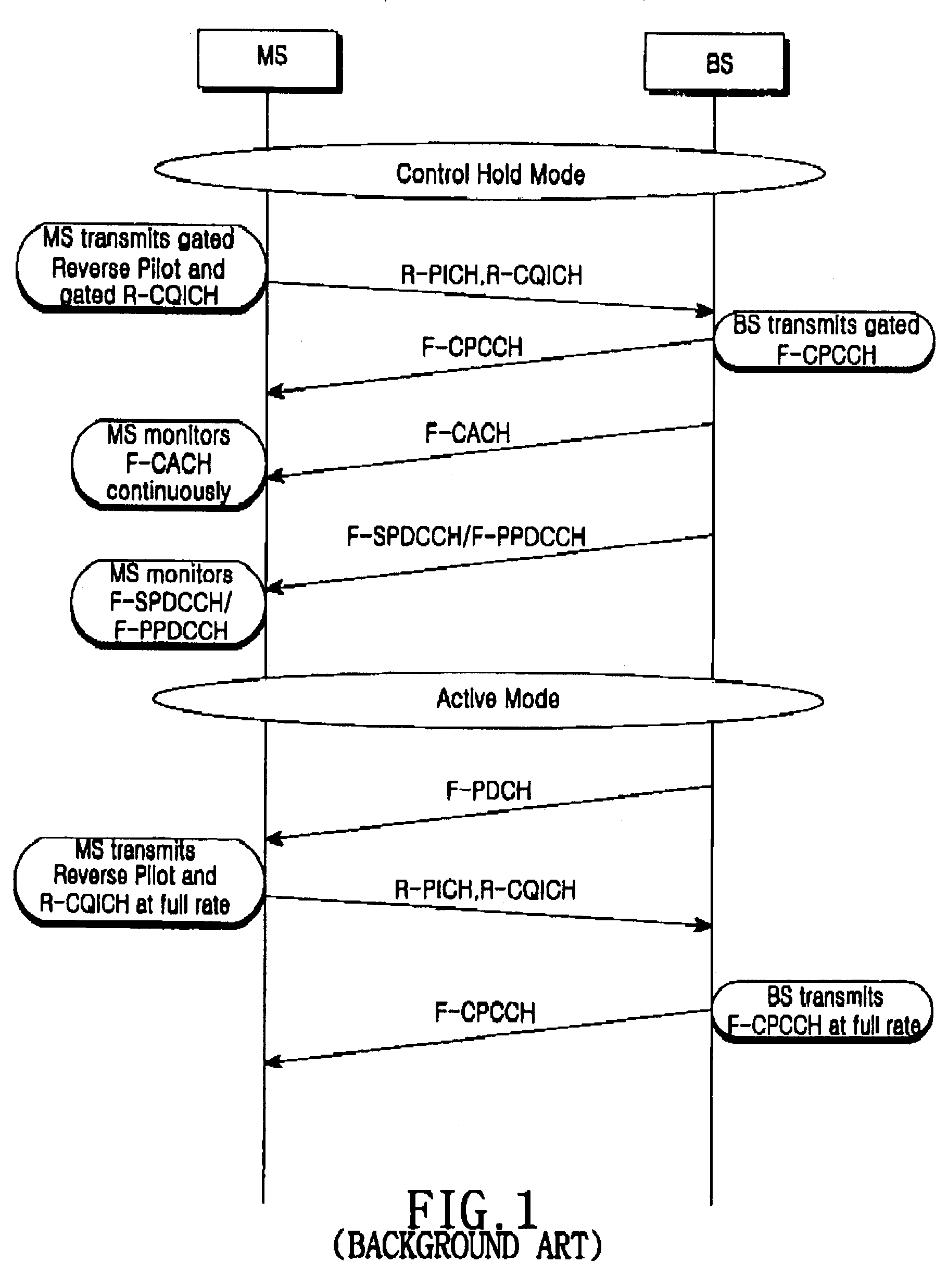
However, in the conventional mode transition method of FIG. 1, the dedicated F-CACH must be allocated between the base station and the mobile station and continuously monitored by the mobile station, causing an increase in power consumption of the mobile station.
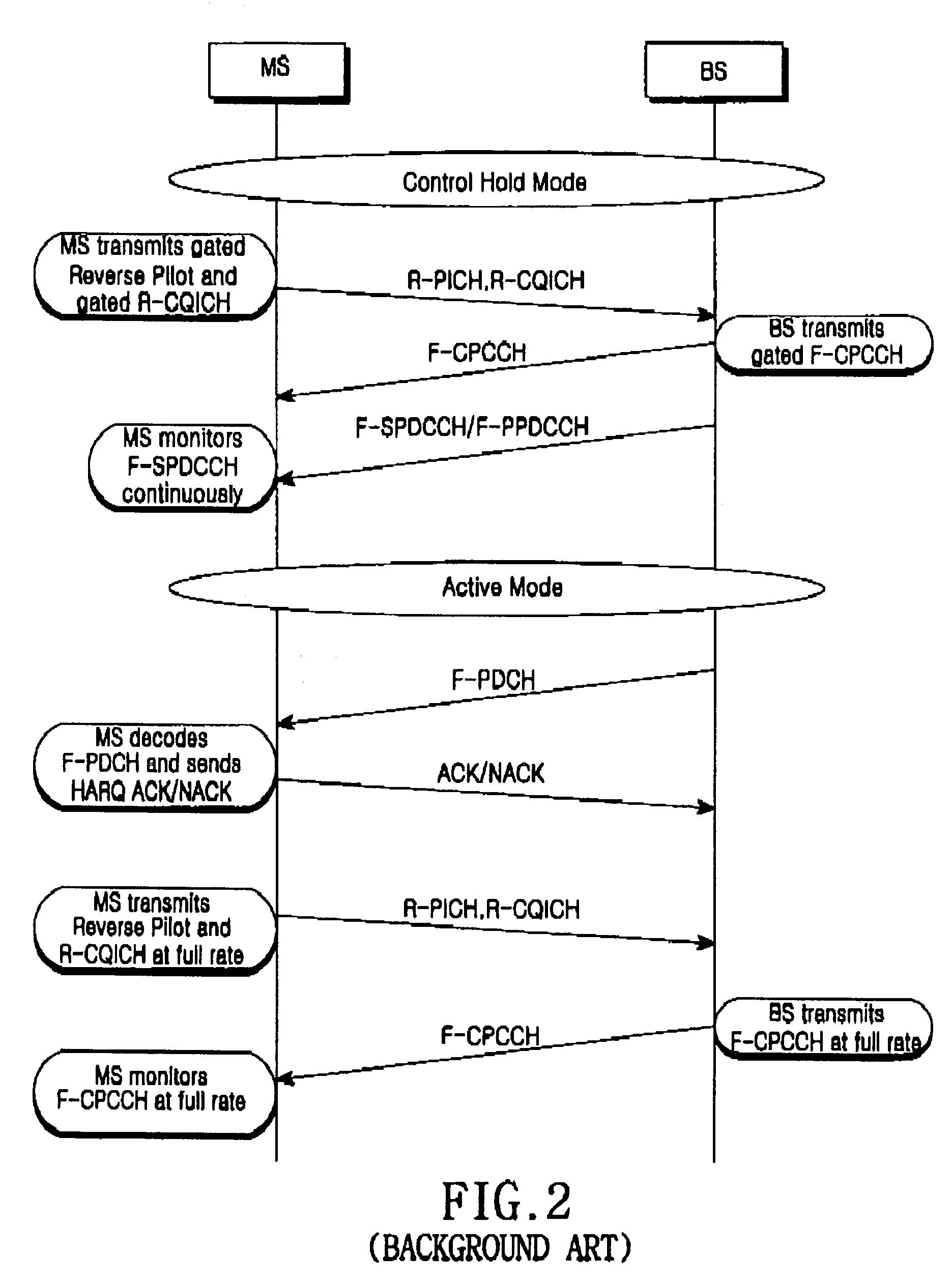
However, even in the mode transition method described in conjunction with FIGS. 2 to 4, the mobile station must continuously monitor F-SPDCCH or F-PPDCCH in the control hold mode without perceiving presence of a mode transition message, thus causing an increase in power consumption of the mobile station.

Method used


Image

  • Mode transition method for wireless data service in a mobile station
  • Mode transition method for wireless data service in a mobile station
  • Mode transition method for wireless data service in a mobile station

Examples


first embodiment

[0050]First, a description will be made of a first embodiment where the WUI transmitted over F-WUCH is comprised of a single indicator bit.

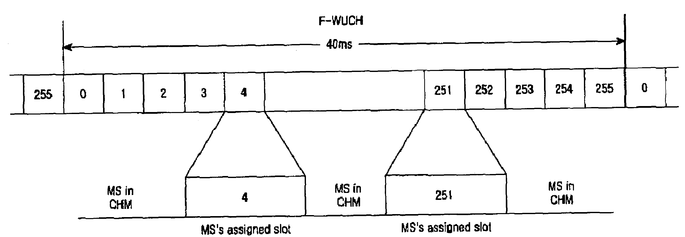
[0051]FIG. 7 illustrates a structure of F-WUCH transmitting a single indicator bit according to a first embodiment of the present invention. Referring to FIG. 7, F-WUCH periodically transmits 40 ms frames each having 256 slots. Each slot has a length of 0.15625 ms, and a particular slot (e.g., a slot with a slot index 128) in each frame is assigned to a particular mobile station. The mobile station in a sleep mode wakes up at the assigned slot to detect an indicator bit, and then returns to the sleep mode if the bit indicates no data. Since the indicator bit has a very short length compared with an F-PDCCH message, a time period where the mobile station wakes up to detect the indicator bit is very short, so that the time period is negligible in terms of power consumption. If the indicator bit does not indicate an instruction for monitoring the F-...

second embodiment

[0057]Next, a description will be made of a second embodiment where the indicator WUI transmitted over F-WUCH is comprised of two indicator bits.

[0058]FIG. 11 illustrates a structure of F-WUCH transmitting two indicator bits according to a second embodiment of the present invention. Referring to FIG. 11, as described in conjunction with FIG. 7, F-WUCH periodically transmits 40 ms frames each having 256 slots. Here, particular slots (e.g., slots with slot indexes 4 and 252) in each frame are assigned to a particular mobile station. The two slots each transmit one indicator bit, and a mode transition condition of a mobile station based on the two indicator bits is illustrated in FIG. 12.

[0059]Referring to FIG. 12, a mobile station in a sleep mode wakes up at a first assigned slot on each frame and detects a first indicator bit. If the detected first indicator bit is “0(OFF),” the mobile station maintains the sleep mode until a first assigned slot on the next frame. Otherwise, if the d...


PUM


Abstract

A mobile station in a control hold mode wakes up at a time slot on a wake-up channel received from a base station, assigned thereto, and detects at least one predetermined indicator bit. If the detected indicator bit indicates that the base station has data to transmit, the mobile station starts monitoring a forward packet data control channel from the base station, in order to determine whether to make a transition to an active mode. Otherwise, if the detected indicator bit indicates that the base station has no data to transmit, the mobile station maintains the control hold mode, thus preventing unnecessary power consumption.

Description

PRIORITY[0001]This application claims priority to an application entitled “Mode Transition Method for Wireless Data Service in a Mobile Station” filed in the Korean Industrial Property Office on Dec. 20, 2001 and assigned Serial No. 2001-82123, and an application entitled “Mode Transition Method for Wireless Data Service in a Mobile Station” filed in the Korean Industrial Property Office on Jan. 4, 2002 and assigned Serial No. 2002-521, the contents of which are incorporated herein by reference herein.BACKGROUND OF THE INVENTION[0002]1. Field of the Invention[0003]The present invention relates generally to a mobile communication system, and in particular, to a method for performing mode transition (or state transition) for a data service in a mobile station.[0004]2. Description of the Related Art[0005]A typical mobile communication system provides only a voice service to a subscriber. However, with the development of the communication technology and at the request of users, studies ...

Claims


Application Information

Patent Timeline
IPC IPC(8): G08C17/00H04B1/38H04B7/26
CPCH04B7/2637H04W76/046H04W72/14H04W76/27Y02D30/70H04W72/23
Inventor KOO, CHANG-HOIBAE, BEOM-SIKPARK, DONG-SEEKKIM, DAE-GYUNJUNG, JUNG-SU
Owner SAMSUNG ELECTRONICS CO LTD
Learn More