
Method and apparatus for storing and reading information in a ferroelectric material

a ferroelectric material and information technology, applied in the field of semiconductor technology, can solve the problems of affecting the polarization of neighboring domains, the risk of alteration of stored information in this domain and adjoining domains, and individual domains that cannot be actuated with sufficient isolation, so as to achieve the effect of easy eras

Inactive Publication Date: 2007-08-28
POLARIS INNOVATIONS LTD
View PDF9 Cites 12 Cited by
  • Summary
  • Abstract
  • Description
  • Claims
  • Application Information

AI Technical Summary

Benefits of technology

"The present invention is about a method and apparatus for storing information in a ferroelectric material. The invention allows for individual domains to be addressed with certainty, and the contact area between the sample probe and the surface of the ferroelectric material can be kept small. The method uses a piezoelectric effect to switch the ferroelectric material, and the contact area between the sample probe and the surface of the material can be as small as the radius of a domain. The invention also allows for the use of a bias to stabilize the stored polarization. The use of a bias ensures permanent storage of information and can be easily erased. The invention provides a way to store information in a ferroelectric material with certainty and high storage density."

Problems solved by technology

A drawback of this practice is that during reading an electrical field acts on the ferroelectric material and this results in the risk of alteration of the stored information in this domain and adjoining domains.
When the information is written into the ferroelectric material using an electrical field, there is likewise the risk that scattering of the electrical field will likewise change the polarization of neighboring domains.
Individual domains therefore cannot be actuated with sufficient isolation.

Method used


Image

  • Method and apparatus for storing and reading information in a ferroelectric material
  • Method and apparatus for storing and reading information in a ferroelectric material
  • Method and apparatus for storing and reading information in a ferroelectric material

Examples


Embodiment Construction

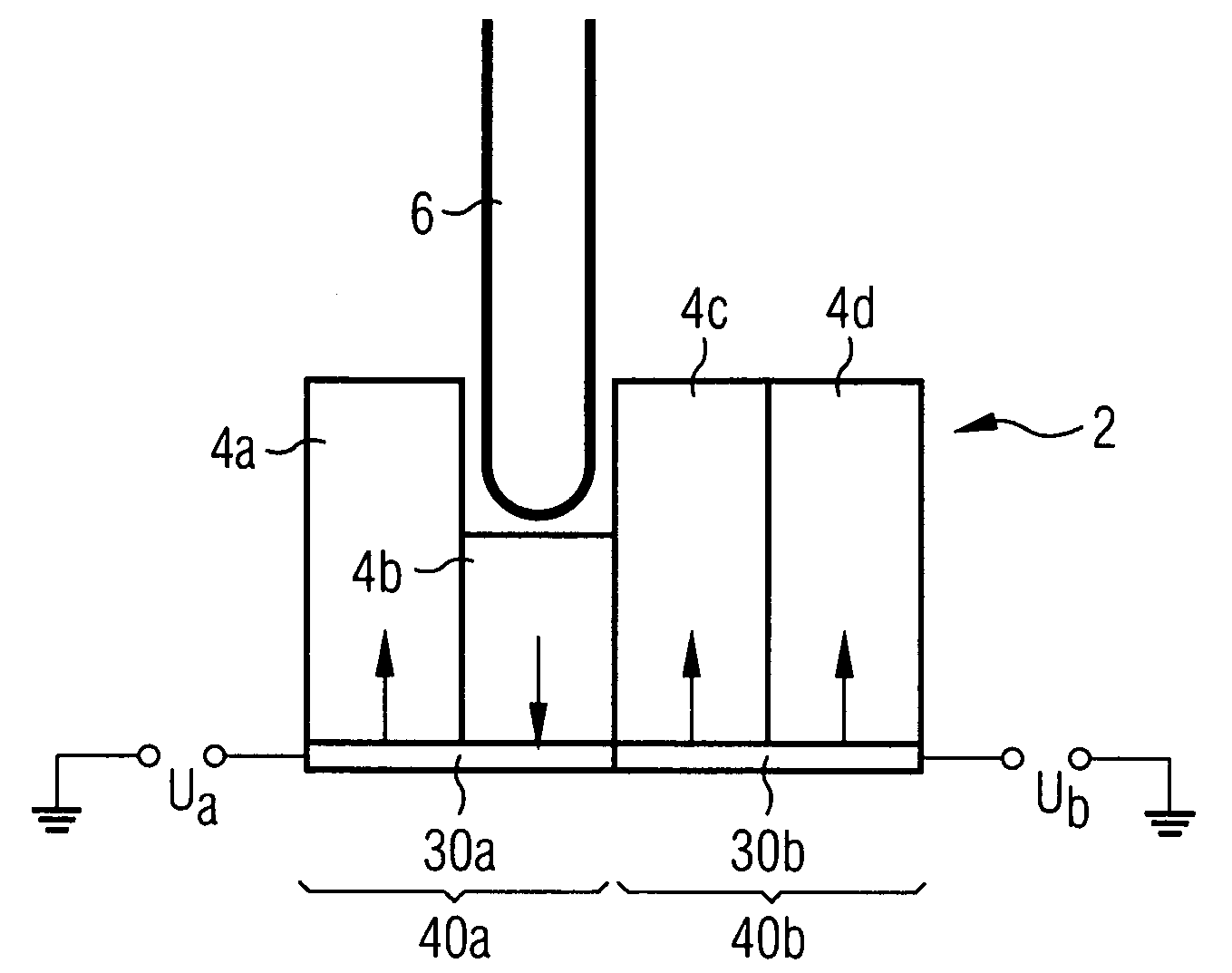
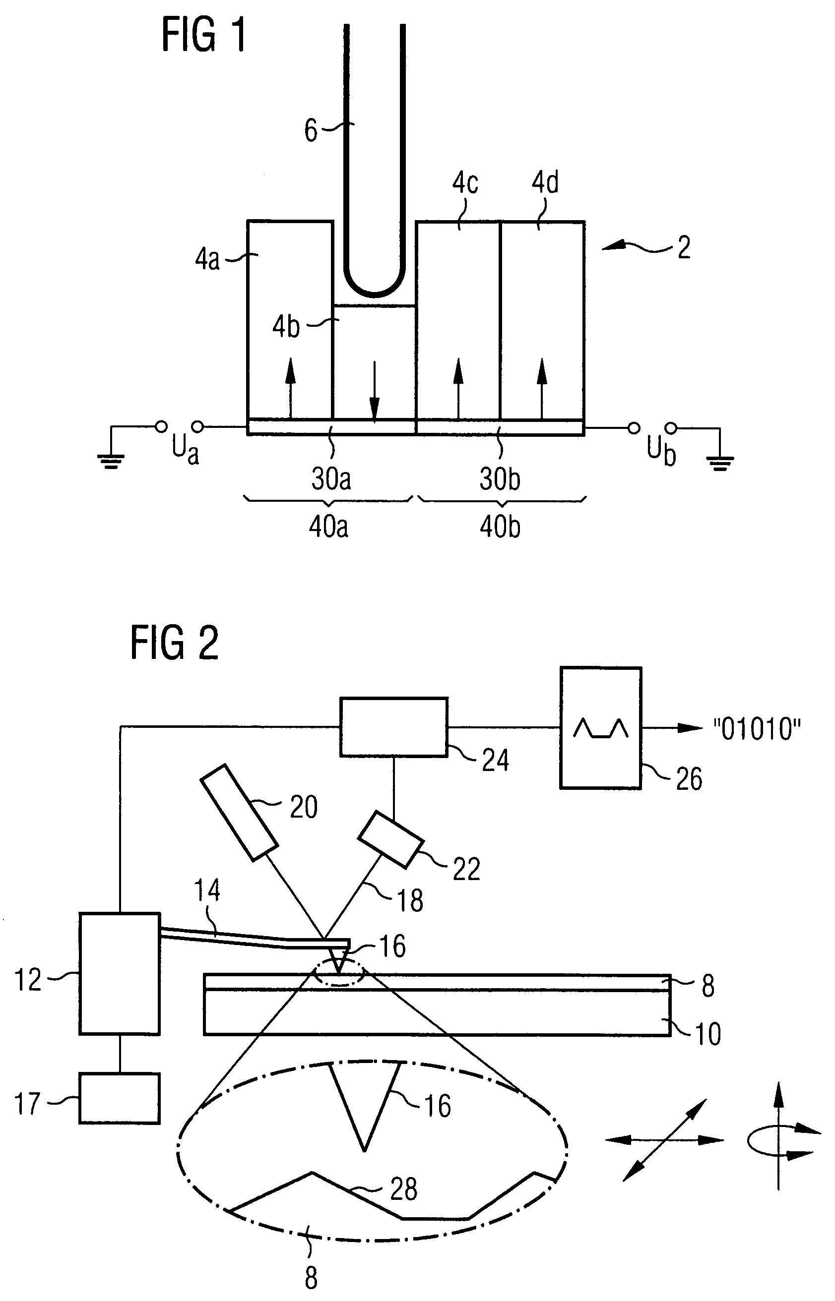
[0057]FIG. 1 shows a ferroelectric material 2 which has a plurality of domains 4a-4d. Arrows indicate the direction of the polarization of the individual domains. A sample probe 6 is used to exert a force on the domain 4b and therefore to bring about a reversal of polarization in this domain.

[0058]The framework of the balanced domain structure is determined essentially during production of the ferroelectric material and particularly during the crystallization. In the case of polycrystalline ferroelectric material, as is normally used, the ferroelectric material comprises a large number of small crystallites (frequently also referred to as grains) with a different orientation in the crystal structure. Spontaneous polarization occurs when the individual crystallites are formed. Areas within individual crystallites having the same polarization are referred to as domains in this context. It is possible for a single domain to form in a crystallite. On the other hand, the formation of a p...


PUM

PropertyMeasurementUnit
structure sizeaaaaaaaaaa
radiusaaaaaaaaaa
thicknessaaaaaaaaaa

Abstract

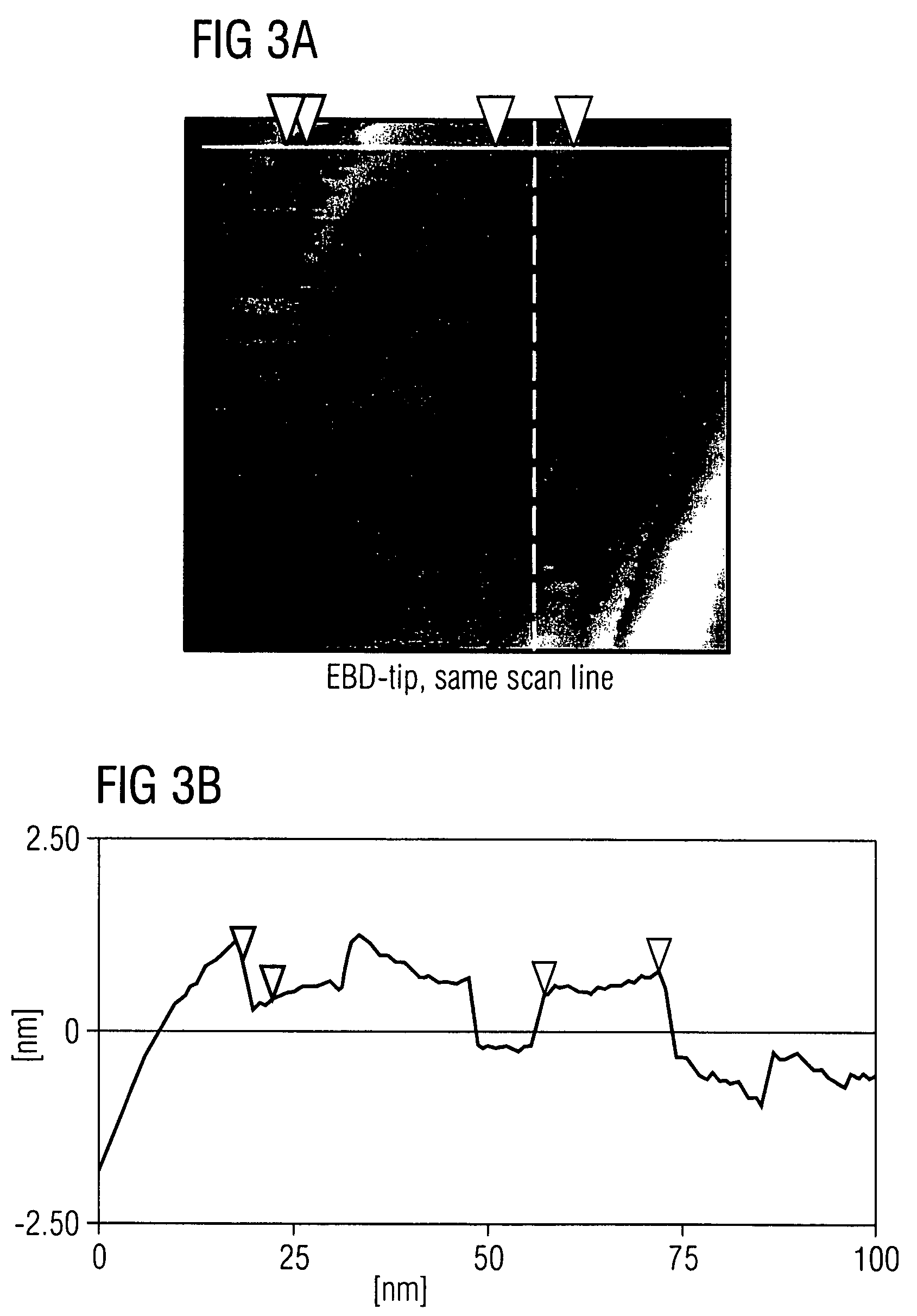
To store information in a ferroelectric material, a sample probe is used to bring about mechanical action on individual domains and thereby to cause a reversal of polarization in the individual domains, with electrodes situated below the ferroelectric material being able to have a bias applied to them to stabilize the change / reversal of polarization. The reversal of polarization causes an alteration in the surface topography of the ferroelectric material, and this alteration can be used to read the information. The stored information is therefore obtained by ascertaining the surface topography of the ferroelectric material. The information is written and read using an AFM tip, with the tip being able to be operated in contact or tapping mode for the purpose of writing, and additionally in noncontact mode for the purpose of reading.

Description

CLAIM FOR PRIORITY[0001]This application is a continuation of PCT / EP03 / 07650, filed Jul. 15, 2003 published in the German language on Jan. 22, 2004, which claims the benefit of priority to German Application No. 102 32 386.0, filed Jul. 17, 2002, which is incorporated herein, in its entirety, by reference.TECHNICAL FIELD OF THE INVENTION[0002]The invention lies in the field of semiconductor technology and relates to a method and apparatus for storing information in a ferroelectric material.BACKGROUND OF THE INVENTION[0003]Information is stored using a multiplicity of different storage media. One of these storage media is ferroelectric materials, which are characterized by spontaneous polarization. The polarization can be changed by applying an electrical field. This is utilized in the case of ferroelectric storage capacitors, for example. Depending on whether the polarization points in one direction or in the opposite direction, the storage capacitor stores a logic 1 or a logic 0.[0...

Claims


Application Information

Patent Timeline
Patent Type & Authority Patents(United States)
IPC IPC(8): G11C11/22G11B9/00G11B9/02G11B11/00G11B11/16
CPCB82Y10/00G11B9/02G11B9/14G11B11/16G11B9/1445G11B9/1463G11B11/007G11B9/1409
Inventor SCHINDLER, GUNTHERVOGEL, MARKUSZYBILL, CHRISTIAN ERICH
Owner POLARIS INNOVATIONS LTD
Learn More