
Method and system for transporting flows of fluid hydrocarbons containing wax, asphaltenes, and/or other precipitating solids

a technology of fluid hydrocarbons and fluid hydrocarbons, which is applied in the direction of separation processes, mechanical equipment, organic chemistry, etc., can solve the problems of affecting local and/or global environmental aspects, entail substantial challenges, and incomplete technology of long distance tieback stops, so as to reduce blockage risks, reduce costs and/or environmental unwanted aspects, and operate simple and steady

Active Publication Date: 2007-08-28
SINVENT AS +2
View PDF7 Cites 36 Cited by
  • Summary
  • Abstract
  • Description
  • Claims
  • Application Information

AI Technical Summary

Benefits of technology

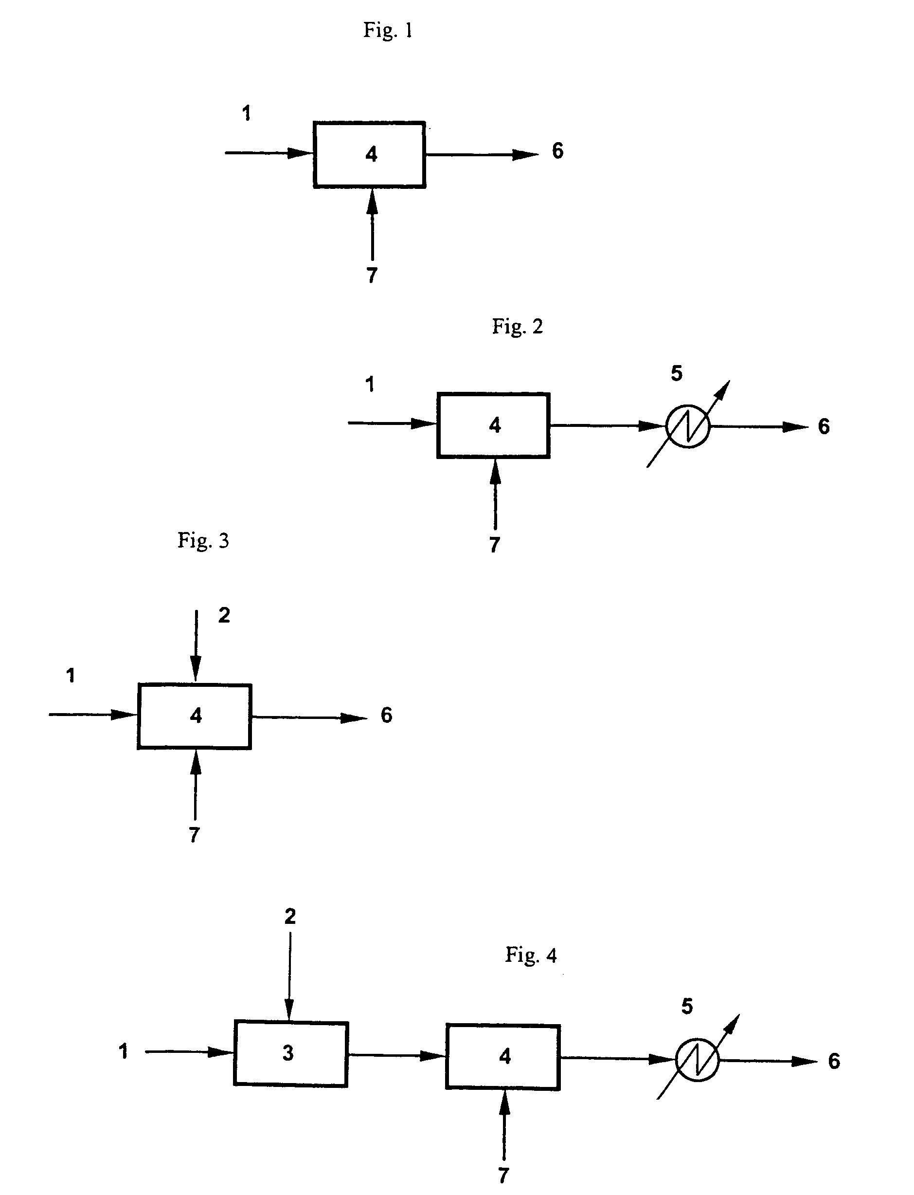
[0020]In the method, wax and / or asphaltenes and / or other precipitating solids (i.e. “precipitors”) are precipitated as small crystals or particles in an oil or condensate containing such precipitors, when a warm fluid flow of oil or condensate containing such non-solidified precipitors is mixed with a cooled fluid flow of oil or condensate containing small wax or asphaltene crystals or particles, or any other small crystals or particles. The crystals or particles in the cooled fluid flow will act as nuclei or growth centers for precipitation of the precipitors in the mixed fluid flow. The temperature in the fluid flow after mixing shall be so low as to provide some degree of supersaturation for crystallization of the precipitors in question. This will increase the precipitation speed of the precipitors on particles present in the fluid flow, decrease the size of new precipitor particles or crystals formed, and prevent or minimize deposits of precipitors on e.g. a subsea pipe wall due to a decreased temperature gradient at the pipe wall. Particles other than wax and / or asphaltene crystals can have the same effect in reducing wall deposition, due to being competing surfaces for the deposition process. The cooled fluid flow of oil or condensate containing small wax or asphaltene crystals or particles, or any other small crystals or particles, may be recycled from the mixed fluid flow or may be any upstream fluid flow.
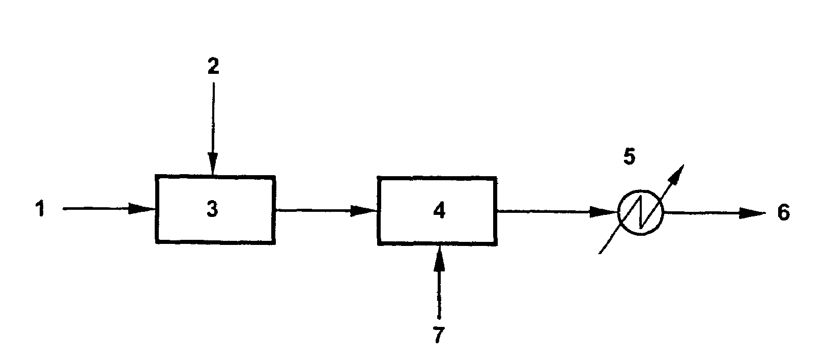
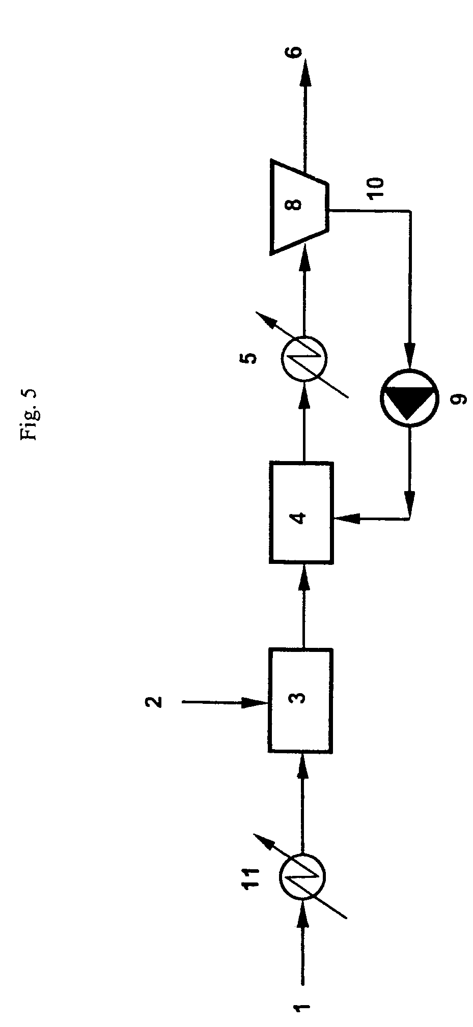
[0021]The flow of warm fluid hydrocarbons containing non-solidified wax and asphaltenes and / or other precipitating solids is introduced into a reactor where it is mixed with a cooled flow of hydrocarbons containing small wax or asphaltene crystals or particles, or any other small crystals or particles, which are also introduced into said reactor. The effluent flow of hydrocarbons from the reactor may be cooled in a heat exchanger to ambient temperature to ensure precipitation of all precipitors, before being conveyed to a pipeline to be transported to its destination, or partly recycled to said reactor. Under certain conditions, the reactor and some downstream pipeline length may be insulated or even actively heated to control the temperature gradient between the fluids and the surroundings, to minimize deposition tendencies.
[0028]The most significant gains from a human safety or environmental viewpoint are that in offshore applications, new surface-piercing structures can be eliminated through enabling direct subsea hydrocarbon production to shore, shallow water or a host platform with available capacity. This type of safer operation removes people from deepwater offshore operations. In addition, the invention is a greener solution, due to the elimination or reduction of many chemical additions. The operational advantages are first of all due to the significant reduction of blockage risks. This means that a host of injection and control systems will become unnecessary for all types of application of the present invention. Successful cold flow means a simpler, steady operation of a low-maintenance system in thermal equilibrium with its surroundings. All of the above factors also contribute towards making cold flow an economically attractive solution. In addition, it seems clear that efficient Cold Flow may be the deciding factor—a project enabler—in terms of getting distant and / or marginal satellite fields to become economically viable. So-called “tiebacks” of producing wells to existing infrastructure is at present restricted to rather short distances, and cold flow will help extend the “reach” from existing installations significantly. It is immediately obvious that leaving out extensive heating or insulation systems is a cost saver, contributing to the commercial potential and usefulness of the present invention.

Problems solved by technology

One of the present key project stoppers for long distance tiebacks is incomplete and very expensive technology for avoiding problems with phase changes in the fluids, and possible deposition in pipelines.
Cold flow, with slurry transport of solidified components, is an attractive solution, but it entails substantial challenges due to the phenomena associated with low-temperature fluid flow.
This has a great impact on system economy, and is often also detrimental to local and / or global environmental aspects.
Alternatively, pipelines for hydrocarbon transport may have to be thoroughly insulated or actively heated (both options are prohibitively expensive), regular scraping operations (pigging) may have to be conducted, or a large amount of fluid processing will have to take place close to the place of production, entailing e.g. complex offshore platform systems or large process facilities for onshore situations.
One challenging problem for cold flow is the presence of paraffinic wax and / or asphaltenes and / or other precipitating solids (i.e. “precipitors”) in many oil or condensate systems.
Deposits of precipitors in pipelines can reduce production (by e.g. blocking conduits completely), reduce system regularity, and may increase costs through lost revenue and workovers by e.g. regular pigging of the pipeline.
1,289,497 stated to be impractical or uneconomic.

Method used


Image

  • Method and system for transporting flows of fluid hydrocarbons containing wax, asphaltenes, and/or other precipitating solids
  • Method and system for transporting flows of fluid hydrocarbons containing wax, asphaltenes, and/or other precipitating solids
  • Method and system for transporting flows of fluid hydrocarbons containing wax, asphaltenes, and/or other precipitating solids

Examples


example i

[0061]In two separate experiments, a crude oil from an offshore production field was circulated in a 50 m long 1″ inner diameter high-pressure steel flow loop in a temperature-controlled environment.

[0062]The flow loop was loaded with an initial volume of about 30 liters of oil which had been cooled quickly in a separate apparatus, to allow formation of initial wax crystals in the bulk phase. When the fluids were transferred, only the free-flowing bulk phase with suspended wax crystals was filled in the loop, and gel or deposits were excluded, thus giving very good initial flowing conditions. The apparent viscosity of the oil phase was estimated to be about 35 cP.

[0063]With the original loading circulating in the loop, at an average rate of approximately 25 liters / minute, injection of fresh oil with all its wax content dissolved in non-crystalline form was started. The injection oil was pre-heated to more than 80° C. for at least 24 hours before being pumped into the circulating col...

example ii

[0072]As one central aspect of the present invention is rapid cooling and production of an easily flowable liquid phase, the apparent viscosity of the same crude oil as used in Example I was studied. A flow loop shaped like a wheel, with a pipe length of about 6.3 m was filled with a certain amount of the oil, and heated to above 80° C. Cooling was then performed as rapidly as possible (somewhere between 40 and 50° C. / hour) to 5° C. The flow loop was rotating with a peripheral velocity of 1 m / s, translating to a shear rate of about 16 s−1. The resulting apparent viscosity—as measured by relating the torque applied to the flow loop rotational axis to keep the rotation speed constant—was between 30 cP and 40 cP.

[0073]The crude oil used in Example I was also tested in the same wheel flow loop after having been used in the experiments in Example I, and showed the same apparent viscosity.


PUM

PropertyMeasurementUnit
diameteraaaaaaaaaa
diameteraaaaaaaaaa
temperatureaaaaaaaaaa

Abstract

A method and a system for transporting a flow of fluid hydrocarbons containing wax and / or asphaltenes or any other precipitating solids through a treatment and transportation system including a pipeline are disclosed. The flow of fluid hydrocarbons is introduced into a reactor (4), where it is mixed with another fluid flow having a temperature below a crystallization temperature for the wax and / or asphaltenes or other solids and containing particles or crystals acting as nucleating and / or growth cores for the wax and / or asphaltenes or other solids, the mixing temperature providing precipitation of the wax and / or asphaltenes or other solids from the flow of fluid hydrocarbons, and the effluent flow of hydrocarbons and particles is conveyed from the reactor (4) to a pipeline (6) for transportation.

Description

INTRODUCTION[0001]The present invention relates to a method and system for reducing undesired deposition of matter in pipelines when transporting cold flows of liquid hydrocarbons containing in particular wax and / or asphaltenes. The concept may, however, also be applicable with regard to many other components contained in oil, gas or formation water and forming solids or deposits under temperature reduction, like but not restricted to; gas hydrates, resins, naphthenates, metal naphthenates, aliphatic aromates, fullerenes, any salts (scale) from formation water, or from any combinations hereof or with wax and asphaltenes. Such components will some times be referred to as “precipitors” in the following text. The inventive concept may also be applicable to reduction of corrosion problems in pipes or processing equipment by binding free water in e.g. gas hydrates. In the method and system of the invention, said flows are transported through a treatment and transportation system includin...

Claims


Application Information

Patent Timeline
Patent Type & Authority Patents(United States)
IPC IPC(8): C10G31/06F17D1/08
CPCF17D1/088
Inventor ARGO, CARL B.BOLLAVARAM, PHANEENDRAHJARBO, KAI W.MAKOGON, TARAS YURIEVICHOZA, NITAWOLDEN, MARITALUND, ARELARSEN, ROAR
Owner SINVENT AS
Learn More