
Direct expansion cooler high velocity dished head

a technology of direct expansion and dished head, which is applied in the direction of indirect heat exchangers, stationary tubular conduit assemblies, lighting and heating apparatus, etc. it can solve the problems of increasing the complexity of installation, reducing the area available for tubes within the shell, and additional stress on the bolts fastening the header to the shell, so as to achieve high refrigerant velocities, less material, and strong attachment

Inactive Publication Date: 2007-08-28
YORK INT CORP
View PDF29 Cites 6 Cited by
  • Summary
  • Abstract
  • Description
  • Claims
  • Application Information

AI Technical Summary

Benefits of technology

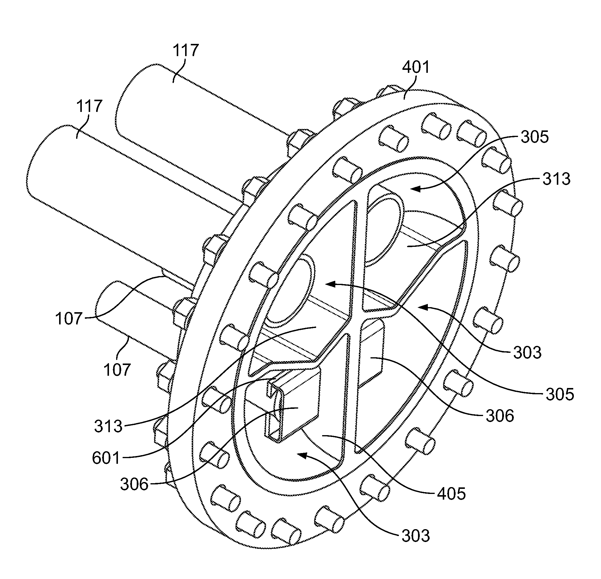
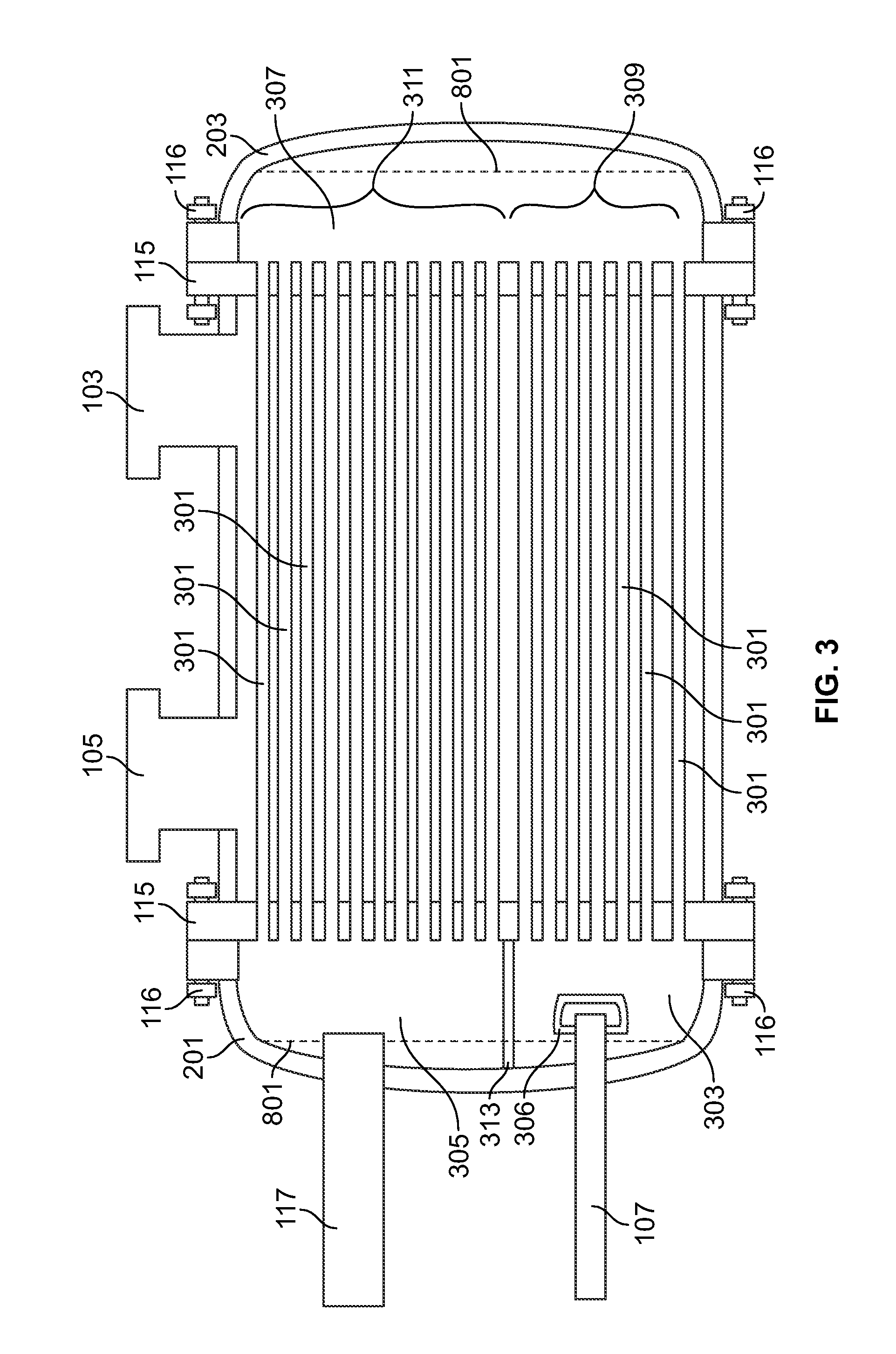
[0008]One advantage of the present invention is that the rounded header geometry provides containment of the refrigerant with less material, stronger attachment to the flange and variable chamber sizes via flow restrictor plates to maintain high refrigerant velocities and high operating efficiency.
[0009]Another advantage of the present invention is that the header assembly only requires a single gasket between the shell and the header. The reduction in the number of gaskets provides a more reliable seal that has reduced leaks and reduced service costs.
[0010]Another advantage of the present invention is the lack of center bolts attaching the header to the shell. Center bolts are not required because of the inherent strength and efficiency of the rounded / dished heads. The removal of the need for center bolts provides a seal that is easier to maintain, provides less stress on the bolts of the flange and provides a greater amount of area in which tubes for heat exchange may be installed.
[0011]Another advantage of the present invention is the attachment of the baffles to the header, providing a single piece for installation. Utilizing a single piece header allows for installation that is simpler and less susceptible to leakage.
[0012]Another advantage of the present invention is that the inlet piping is attached to the header and extended into the inlet and outlet chambers for more direct flow, increasing the velocity of the refrigerant and efficiency of the operation of the heat exchanger. In addition, the extended nozzles are easier and less costly to fabricate. Diffusers at the end of the extended nozzles facilitate efficient operation and improve performance.
[0013]Another advantage of the present invention is that the baffles may be arranged in a plurality of configurations, which can adjust the size of the chambers within the head. Adjustment of the chamber size provides control of the velocity of the refrigerant and residence time of the refrigerant in the header. The control of the velocity and residence time allows the header to be customized to the particular application and / or retrofitted to existing heat exchangers.

Problems solved by technology

The divider requires bolts that fasten the divider to the end of the shell, adding to the complexity of installation, requiring additional gaskets, reducing the area available for tubes within the shell, and causing additional stress on the bolts fastening the header to the shell.
These chiller heat exchangers have the additional drawback that multiple gaskets are required, thus increasing the occurrences of leakage of refrigerant and increasing the service costs.
These chiller heat exchangers have the further drawback that the flat plate on the header is relatively thick and heavy, thereby increasing material cost and weight of the system.
However, these center bolts are generally overstressed and result in additional leakage paths and cost.

Method used


Image

  • Direct expansion cooler high velocity dished head
  • Direct expansion cooler high velocity dished head
  • Direct expansion cooler high velocity dished head

Examples


Embodiment Construction

[0030]HVAC systems may include refrigerant circuits having a compressor, a condenser, and an evaporator connected in a refrigerant loop. Refrigerant is circulated through the refrigerant loop to the various components. The compressor compresses refrigerant vapor and delivers it to the condenser. The refrigerant vapor delivered by the compressor to the condenser enters into a heat exchange relationship with water or other suitable heat exchange fluid, heating the water while undergoing a phase change to a refrigerant liquid as a result of the heat exchange relationship with the water. The refrigerant leaves the condenser and is delivered to an evaporator. One type of evaporator or cooler is referred to as a chiller heat exchanger, commonly referred to as a direct expansion heat exchanger. The chiller heat exchanger places the liquid refrigerant from the condenser into a heat exchange relationship with a fluid, typically water, and undergoes a phase change to a refrigerant vapor as a ...


PUM

PropertyMeasurementUnit
volumeaaaaaaaaaa
thickaaaaaaaaaa
stressaaaaaaaaaa

Abstract

A dished head header assembly for a heat exchanger having a containment body that includes a rounded, or dished, wall portion forming an interior cavity. A flange attaches to the containment body and fastens the header assembly to the heat exchanger. A plurality of refrigerant passageways are extended through an opening in the containment body into the interior cavity. At least one baffle is attached to the rounded wall portion. The baffle divides the interior cavity into a plurality of sub-cavities. At least one divider divides the sub-cavities into a plurality of chambers. The plurality of passageways includes an inlet connection and an outlet connection for a plurality of refrigerant circuits. Each passageway is disposed in a corresponding chamber of the plurality of chambers. Extensions into the headers with diffusers insure efficient operation and performance of the heat exchanger. The adjustable flow restrictor plate maintains optimum velocities to further enhance performance.

Description

FIELD OF THE INVENTION[0001]The present invention is directed to shell and tube heat exchangers. In particular, the present invention is directed to headers for shell and tube heat exchangers used with heating ventilation and air conditioning (HVAC) systems.BACKGROUND OF THE INVENTION[0002]Shell and tube heat exchangers typically include headers on each end of the shell in order to provide access to the tubes within the shell for cleaning or service. The headers also provide containment for refrigerant or heat exchange fluid and provide the refrigerant or heat exchange fluid to the tubes. Chiller systems typically include a chiller heat exchanger, which is a shell and tube heat exchanger having a refrigerant flow in the tubes and heat exchange fluid, such as water, flowing in the shell. Each end of the chiller heat exchanger includes a header fastened to the shell. The header includes a flat head plate and a baffle chamber. The head plate is a flat, thick plate that provides contain...

Claims


Application Information

Patent Timeline
Patent Type & Authority Patents(United States)
IPC IPC(8): F28F9/02
CPCF28D7/1607F28F9/0265F28F9/0202Y10T29/49361
Inventor ROHRBAUGH, DARYL EUGENEGORDON, JOEL I.
Owner YORK INT CORP
Learn More