
Masked digital signatures

a digital signature and mask technology, applied in the field of mask digital signatures, can solve the problems of slow signature and verification, computationally intensive cryptosystems, and delay in the signature and verification process, and achieve the effect of slowing down the signature and verification process, and reducing the computational intensity of the computation

Inactive Publication Date: 2007-08-21
CERTICOM
View PDF11 Cites 9 Cited by
  • Summary
  • Abstract
  • Description
  • Claims
  • Application Information

AI Technical Summary

Benefits of technology

[0019]It is therefore an object of the present invention to provide a method and apparatus in which at least some of the above disadvantages are mitigated.
[0020]This invention seeks to provide a digital signature method, which may be implemented relatively efficiently on a processor with limited processing capability, such as a ‘smart card’ or the like.
[0021]In general terms, the present invention provides a method and apparatus in which signature verification may be accelerated.

Problems solved by technology

For example given the elliptic curve group E(Fq) then for P ∈E(Fq) and Q=aP the discrete logarithm problem reduces to finding the integer a. Thus these cryptosystems can be computationally intensive.
Where either party has adequate computing power this does not present a particular problem but where one or both the parties have limited computing power, such as in a ‘smart card’ application, the computations may introduce delays in the signature and verification process.
Other protocols, such as the MQV protocols also require similar computations when implemented over elliptic curves which may result in slow signature and verification when the computing power is limited.
These steps are computationally complex and therefore require either significant time or computing power to perform.
This however cannot be done directly on the ECDSA signature scheme without potentially compromising the private key information.

Method used


Image

  • Masked digital signatures
  • Masked digital signatures
  • Masked digital signatures

Examples


Embodiment Construction

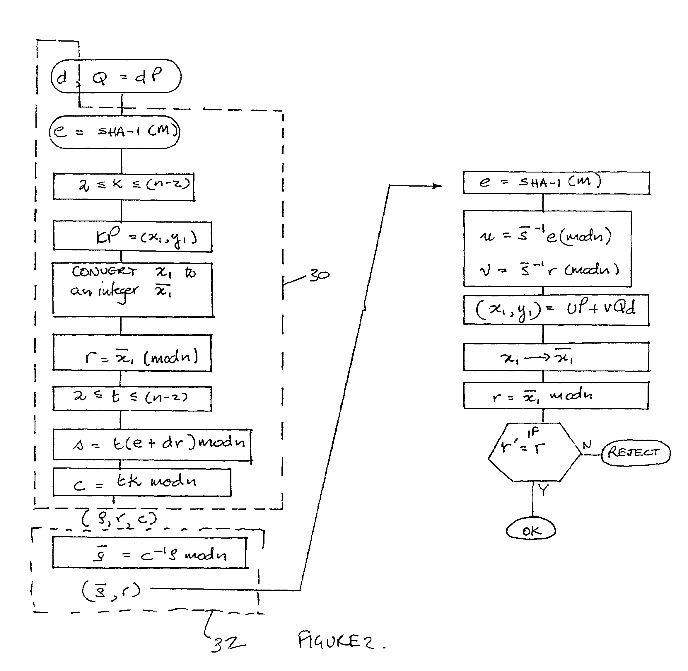
[0026]Referring therefore to FIG. 1, a data communication system 10 includes a pair of correspondents, designated as a sender 12, and a recipient 14, who are connected by a communication channel 16. Each of the correspondents 12,14 includes an encryption unit 18,20 respectively that may process digital information and prepare it for transmission through the channel 16 as will be described below. The sender is the party signing a message m to be verified by the recipient. The signature is generally performed in the encryption unit 18 and normally defines a secure boundary. The sender could be a ‘smart card’, a terminal or similar device. If for example the signor is a ‘smart card’, it generally has limited processing power. However, the ‘smart card’ is typically used in conjunction with a terminal 22 which has at least some computing power. The ‘smart card’ is inserted into a terminal 22 which then forwards digital information received from the ‘smart card’12 along the channel 16 to ...


PUM


Abstract

The present invention relates to digital signature operations using public key schemes in a secure communications system and in particular for use with processors having limited computing power such as ‘smart cards’. This invention describes a method for creating and authenticating a digital signature comprising the steps of selecting a first session parameter k and generating a first short term public key derived from the session parameter k, computing a first signature component r derived from a first mathematical function using the short term public key, selecting a second session parameter t and computing a second signature component s derived from a second mathematical function using the second session parameter t and without using an inverse operation, computing a third signature component using the first and second session parameters and sending the signature components (s, r, c) as a masked digital signature to a receiver computer system. In the receiver computer system computing a recovered second signature component s′ by combining a third signature component with the second signature component to derive signature components (s′, r) as an unmasked digital signature. Verifying these signature components as in a usual ElGamal or ECDSA type signature verification.

Description

[0001]This is a continuation of U.S. application Ser. No. 08 / 966,702, filed Nov. 10, 1997.[0002]This invention relates to a method of accelerating digital signature operations used in secure communication systems, and in particular for use with processors having limited computing power.BACKGROUND OF THE INVENTION[0003]One of the functions performed by a cryptosystem is the computation of digital signatures that are used to confirm that a particular party has originated a message and that the contents have not been altered during transmission. A widely used set of signature protocols utilizes the ElGamal public key signature scheme that signs a message with the sender's private key. The recipient may then recover the message with the sender's public key. The ElGamal scheme gets its security from calculating discrete logarithms in a finite field. Furthermore, the ElGamal-type signatures work in any group and in particular elliptic curve groups. For example given the elliptic curve gro...

Claims


Application Information

Patent Timeline
IPC IPC(8): H04L9/00G09C1/00G07F7/10H04L9/32
CPCG06Q20/341G06Q20/40975G07F7/1008H04L9/3247H04L9/3252H04L9/3066H04L2209/04
Inventor JOHNSON, DONALD B.VANSTONE, SCOTT A.OU, MINGHUA
Owner CERTICOM
Learn More