Recording apparatus

Active Publication Date: 2007-08-07
BROTHER KOGYO KK
View PDF9 Cites 3 Cited by
  • Summary
  • Abstract
  • Description
  • Claims
  • Application Information

AI Technical Summary

Benefits of technology

[0010]The present invention was developed in the light of the situations described above, and therefore it is an object of the invention to provide a recording apparatus capable of efficiently releasing heat generated at the driver element of the printing head, which driver element is disposed on the flexible wiring board, while preventing the driver element from being damaged even if a foreign material is introduced between the heatsink and the driver element where a degree of closeness of the contact between the heatsink and the driver element is enhanced.
[0012]In the recording apparatus according to the above-indicated first preferred form of the invention, the flexible wiring board having the driver element for driving the printing head is disposed on the outer side of the head holder, while the heatsink is disposed between the flexible wiring board and the head holder. Accordingly, it is made easy for the heatsink disposed between the flexible wiring board and the head holder to extend to have a sufficient surface area for releasing outward the heat generated by the driver element, thereby making it possible to inhibit a rapid rise in temperature of the driver element.
[0014]In the recording apparatus according to the second preferred form of the invention, the heatsink is held in close contact with the surface of the flexible wiring board which surface is opposite to the another surface on which the driver element is disposed, at the position corresponding to the position in the another surface where the driver element is disposed. Since the flexible wiring board is an insulating body having a flexibility, even in the case where a foreign material is introduced between respective contact portions of the heatsink and the flexible wiring board which are in close contact with each other, the foreign material sinks into or sticks in the surface portion of the flexible wiring board, holding the heatsink in close contact with the surface of the flexible wiring board which surface is opposite to the surface on which the driver element is disposed. Accordingly, the driver element is not subjected to a local force which may damage the driver element, and a high heat conductivity is achieved. It is noted that the same advantages can be obtained even if a member is interposed between the heatsink and the flexible wiring board.

Problems solved by technology

Due to the existing tendency that the number of the nozzles increases and density thereof also increases, wiring between a driver IC chip as the driver element generating drive signals and a printing head becomes thinner and denser, making the drive signals on the wiring susceptible to noise.
However, such an increase leads to a larger amount of heat generated at the driver IC chips, and accordingly requires enlarging the heatsink.
Further, in a case where the head holder has a small size, the size of the heatsink is limited and therefore the heat generated at the driver IC chips can not be effectively released.
In this case, performance of the driver IC chips may be deteriorated, or the driver IC chips may be damaged.
If such introduction of a foreign material occurs, the driver IC chip may be damaged, since the driver IC chip is pressed onto the heatsink by the elastic member and subjected to a local pressure due to the presence of the foreign material.
In addition, the foreign material introduced between the heatsink and the driver IC chip deteriorates close contact between the heatsink and the driver IC chip, lowering heat conduction from the driver IC chip to the heatsink.
Further, since a surface of the driver IC chip functions as a ground electrode, when an electrical noise which deteriorates print quality occurs at one of the driver IC chips, the noise is propagated to other driver IC chips through the heatsink.

Method used


Image

  • Recording apparatus
  • Recording apparatus
  • Recording apparatus

Examples


Embodiment Construction

[0026]Referring to the accompanying drawings, there will be described preferred embodiments of the present invention.

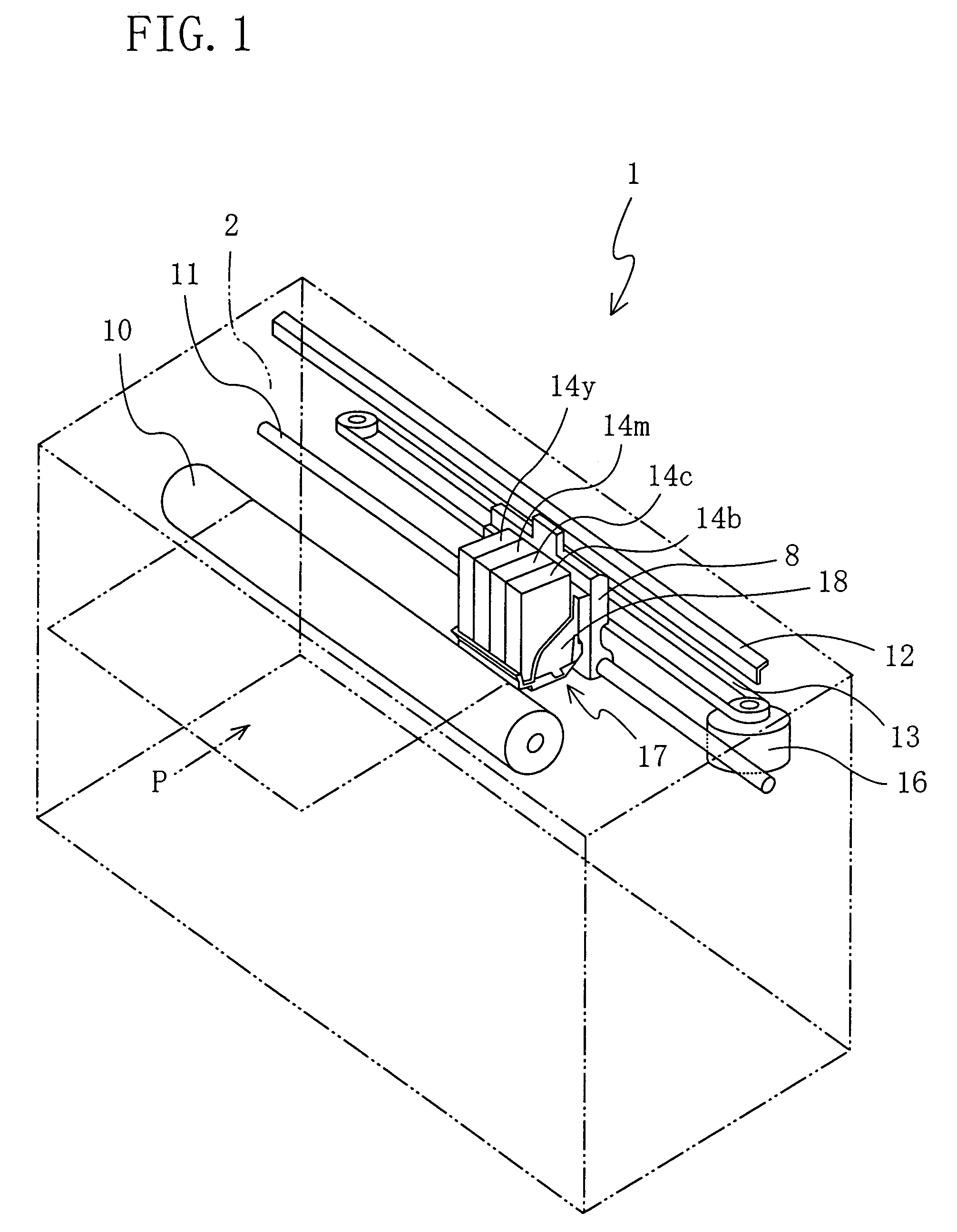
[0027]Referring first to FIG. 1, there will be first described internal structure of an ink jet printer 1 according to a first embodiment of the present invention. FIG. 1 is a perspective view showing the internal structure of the ink jet printer 1.

[0028]As shown in FIG. 1, a carriage 8, which is moved in reciprocation motion in the widthwise direction of a sheet P of paper as the printing medium, is disposed in a housing 2 of the ink jet printer 1. The carriage 8 is slidably supported by a guide rod 11 and a guide member 12 which extend in a longitudinal direction of the housing 2, and is fixed to an endless belt 13 wound around two pulleys and extending in the longitudinal direction of the housing 2. When the endless belt 13 is circulated or driven by a carriage motor 16, the carriage 8 is reciprocated along the guide rod 11, i.e., in a direction parallel to the she...


PUM


Abstract

A recording apparatus comprising: a printing head which has a plurality of recording elements and performs recording on the recording medium; a head holder which holds the printing head; a flexible wiring board comprising a flexible insulating band and a plurality of conductive wires and a driver element for actuating the printing head, which are provided on the flexible insulating band; and a heatsink for releasing heat generated by the driver element, wherein the heatsink is disposed between the flexible wiring board and the head holder.

Description

[0001]The present application is based on Japanese Patent Application Nos. 2003-089882 and 2003-089899 both filed on Mar. 28, 2003, the contents of which are incorporated herein by reference.BACKGROUND OF THE INVENTION[0002]1. Field of the Invention[0003]The present invention relates in general to a recording apparatus. In particular, the invention relates to an ink jet recording apparatus having a printing head to record a desired image on a recording medium, a driver element for driving the printing head, and a flexible wiring board for transmitting signals from the driver element to the printing head.[0004]2. Discussion of Related Art[0005]There is conventionally known an ink-jet recording apparatus for recording a desired image on a recording medium such as a sheet of paper, which apparatus is adapted to eject, onto the recording medium, a droplet of ink through a plurality of nozzles formed in a printing head so that the desired image is formed on the recording medium. On the i...

Claims


Application Information

Patent Timeline
IPC IPC(8): B41J29/377B41J2/14B41J2/175H05K1/14
CPCB41J2/1408B41J2/17526B41J2/17553B41J2202/08H05K1/147
Inventor KATAYAMA, NAOKI
Owner BROTHER KOGYO KK
Why Eureka
Try Eureka