
Overcurrent limiting controller

a technology of overcurrent protection and limiter, which is applied in the direction of motor/generator/converter stopper, pulse technique, instruments, etc., can solve the problem of inability to solve the erroneous judgment problem of the overcurrent protection function to the inrush current as described above, and the inability to start the motor at all

Inactive Publication Date: 2007-07-17
DENSO CORP
View PDF4 Cites 15 Cited by
  • Summary
  • Abstract
  • Description
  • Claims
  • Application Information

AI Technical Summary

Benefits of technology

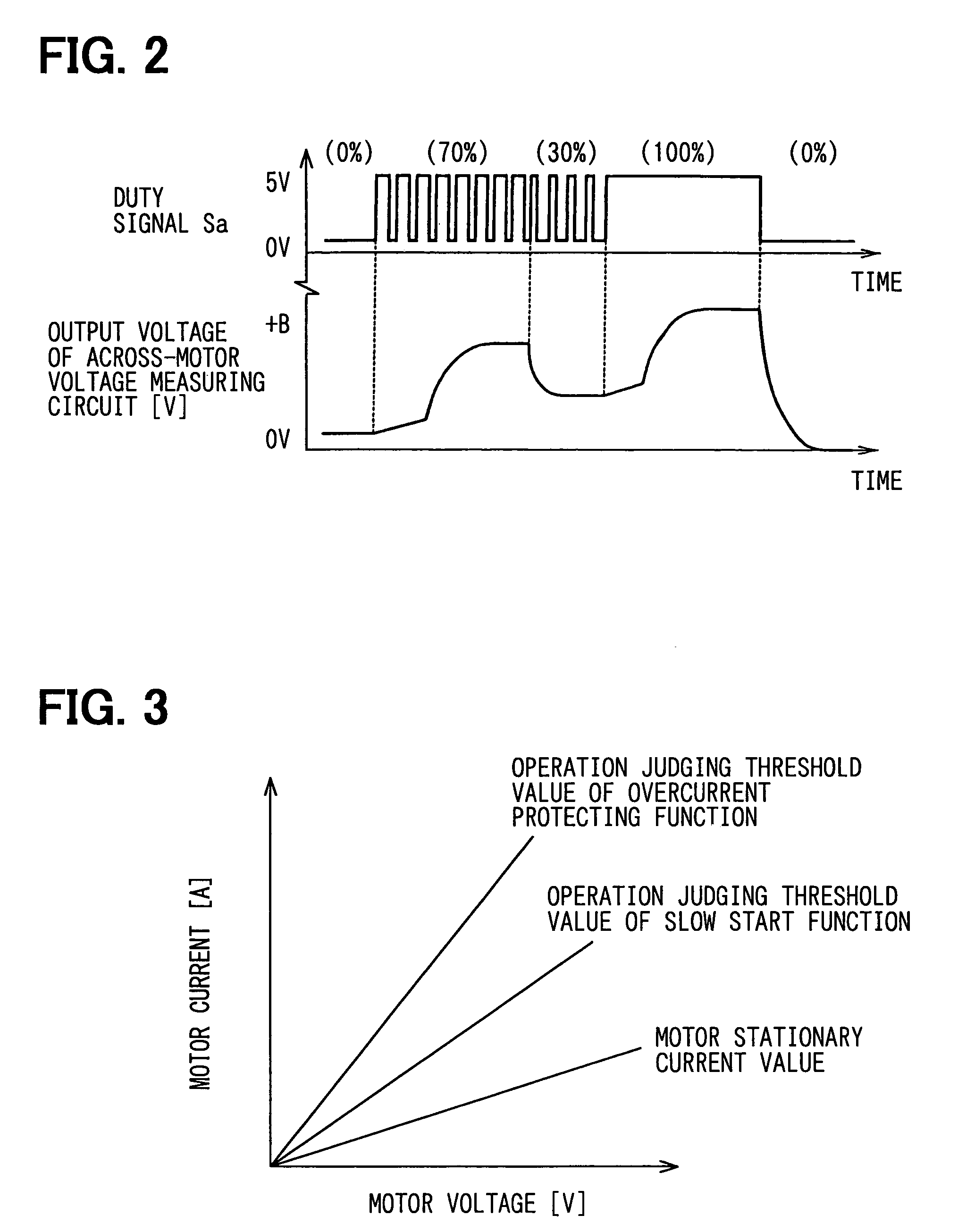
The patent text describes a semiconductor device controller that can switch its response to changes in the input signal in a way that prevents overcurrent and delays the operation of the load. The controller uses a current level judging unit to compare the current with a small judgment value and change the circuit time constant accordingly. This prevents malfunctions caused by overcurrent and ensures stable operation. The current level judging unit also takes into account the voltage applied to the load, which is a more accurate measure of the current. The overcurrent judging unit and the current level judging unit work together to prevent the judgment result from being switched too quickly. The current detecting unit uses the ON-resistance of the semiconductor device, which simplifies the construction of the circuit. The time constant changing unit can be activated during the interrupt period of the semiconductor device, and the output state of the time constant changing instruction is held for a fixed time period to prevent rapid changes in the circuit time constant.

Problems solved by technology

This system is effective to prevent the erroneous judgment of the protection function of the overcurrent, however, it is difficult to apply it to a system to which relatively high response is required.
However, in the technique disclosed in the above publication, it is merely supposed that the switching operation of the response is carried out only at the start time of the motor, and the subsequent switching operation of the input signal is carried out with high response at all times. Accordingly, the erroneous judgment problem of the overcurrent protection function to the inrush current as described above can be never solved.
However, in the technique disclosed in the above publication, the response is lowered at the start of the motor at all times, and thus the start of the motor is delayed at all times irrespective of whether the inrush current flowing at the start of the motor actually occurs at such level that the erroneous judgment occurs.

Method used


Image

  • Overcurrent limiting controller
  • Overcurrent limiting controller
  • Overcurrent limiting controller

Examples


first embodiment

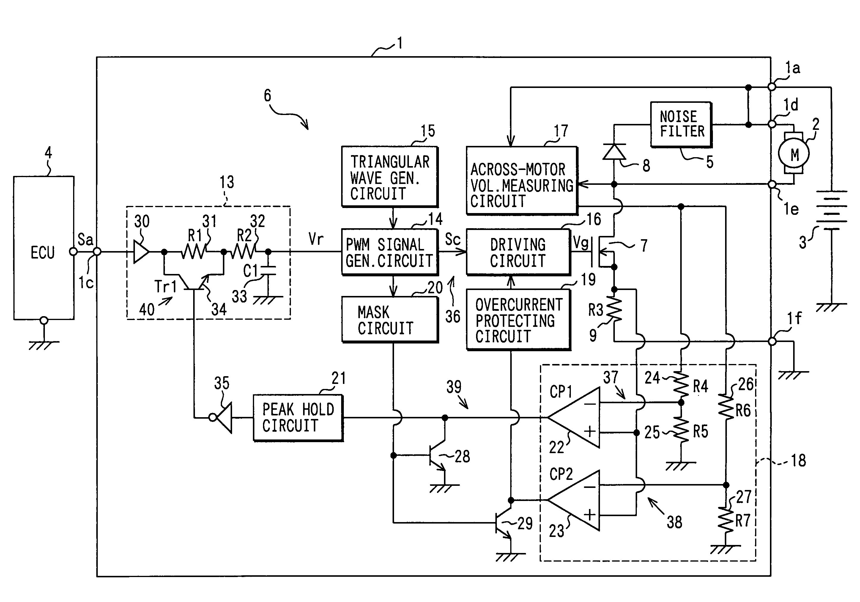
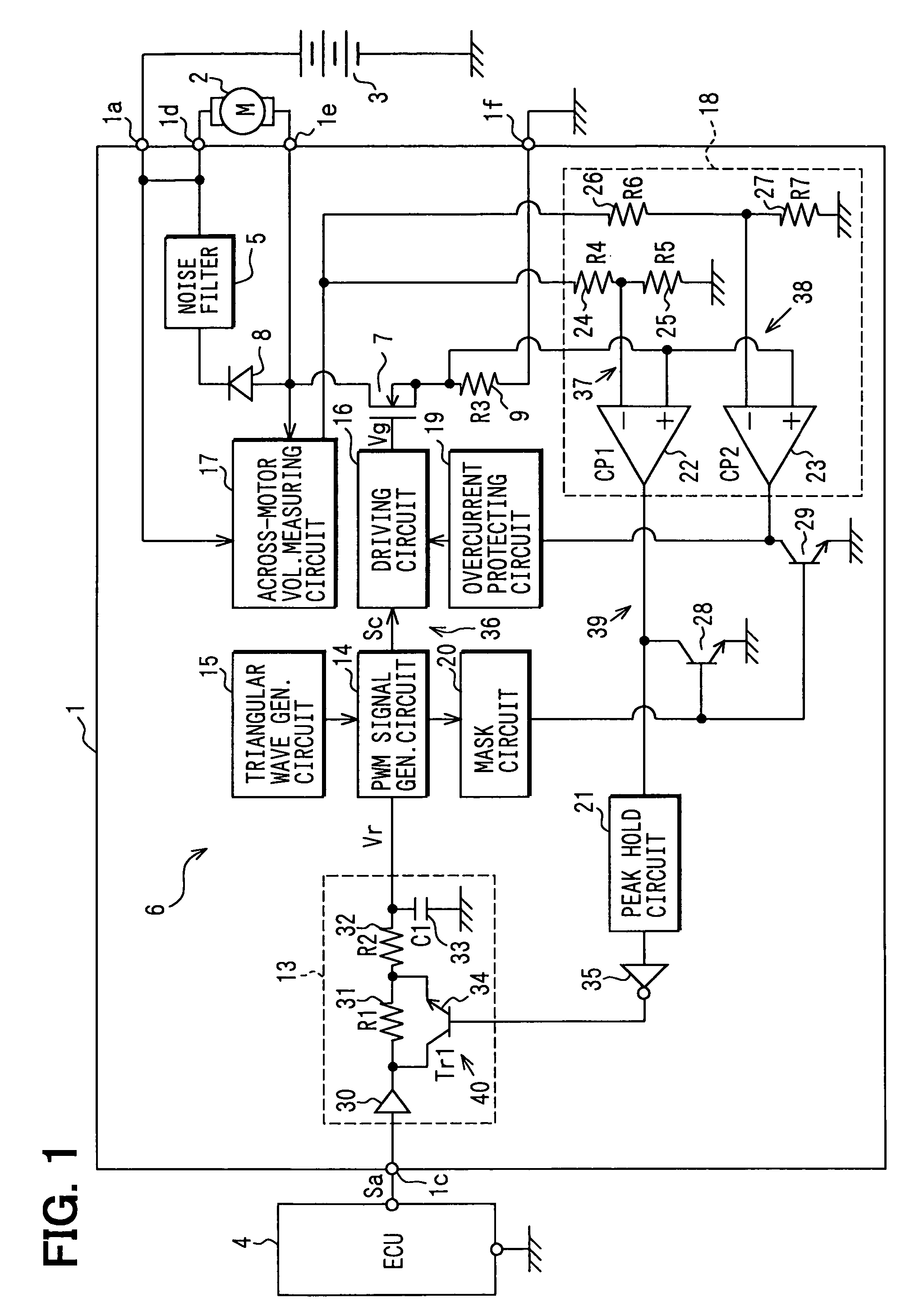
[0033]A first embodiment in which the controller is applied to a device for driving an air blowing fan motor of a heat exchange in a cooling system for a vehicle will be described with reference to FIGS. 1 to 4. FIG. 1 shows the electrical construction of a motor driving device. The motor driving device 1 drives an air blowing fan motor 2 (hereinafter referred to as motor 2), and it operates with a battery voltage supplied from a battery 3 to a terminal 1a as a power source voltage +B. Furthermore, an instruction signal Sa is supplied from an engine ECU 4 (Electronic Control Unit) to a terminal 1c. The instruction signal Sa is a PWM signal whose duty is varied in accordance with a voltage to be applied to the motor (load) 2.

[0034]The ECU 4 concentratively controls plural controllers for an engine such as fuel injection control, ignition timing control, idle rotational speed control, etc. As not shown, the ECU 4 is supplied with various signals such as a temperature signal of engine ...

second embodiment

[0057]FIG. 5 shows a second embodiment. In FIG. 5, the same parts as in the first embodiment are represented by the same reference numerals, and the description thereof is omitted. Only the different parts from the first embodiment will be described hereunder. A FET controller 41 of the second embodiment by which the FET controller 6 is replaced is achieved by replacing the input signal processing circuit 13 with an input signal processing circuit 42. That is, in the input signal processing circuit 13, the resistance elements 31 and 32 are inserted in the input signal in series. However, in the input signal processing circuit 42, the series circuit comprising the transistor 34 and the resistance element 32 is connected to the resistance element 31 in parallel. These elements constitute a time constant switching unit 40a, and the other construction is the same as the first embodiment.

[0058]According to the second embodiment thus constructed, under the state that the transistor 34 is ...

third embodiment

[0059]FIG. 6 shows a third embodiment, and only the different parts from the first embodiment will be described hereunder. In an FET controller 43 of the third embodiment, the resistance element 9 for current detection is eliminated, and the non-inverting input terminals of the comparators 22 and 23 are connected to the drain of MOSFET 7. According to the third embodiment thus constructed, the current flowing in the motor 2 can be detected by utilizing the ON-resistance when FET (current detecting unit) 7 is turned on in place of the resistance element 9. Accordingly, the construction can be more simplified.


PUM


Abstract

A semiconductor device controller includes a current supply control unit for controlling a conduction state of a semiconductor device connected to a load in response to a control signal to supply current to the load, a current level judging unit for comparing one or more switching judgment values set in an area smaller than an overcurrent judgment value with current detected by a current detecting unit to carry out a current level judgment and a time constant changing unit for changing the circuit time constant of the input signal processing circuit in accordance with a judgment result by the current level judging unit.

Description

CROSS REFERENCE TO RELATED APPLICATIONS[0001]This application is based upon, claims the benefit of priority of, and incorporates by reference the contents of, Japanese Patent Application No. 2004-284060 filed on Sep. 29, 2004 and Japanese Patent Application No. 2005-110077 filed on Apr. 6, 2005.FIELD OF THE INVENTION[0002]The present invention relates to a semiconductor device controller for controlling a semiconductor device for processing a pulse signal input as a current supply instruction from the outside on the basis of a circuit time constant to generate a control signal, and supplying current to a load in accordance with the control signal thus generated.BACKGROUND OF THE INVENTION[0003]In many cases, the value of a device for controlling a semiconductor device in accordance with an instruction signal input from the outside to supply current to a motor and drive the motor is enhanced by providing the device with such a protecting function that overcurrent (current extremely l...

Claims


Application Information

Patent Timeline
Patent Type & Authority Patents(United States)
IPC IPC(8): H03K3/00
CPCH02P1/18
Inventor NAKAMURA, KOJI
Owner DENSO CORP
Learn More