
Calibration method for radiation detector, and particle therapy system

Active Publication Date: 2013-08-29
HITACHI LTD
View PDF0 Cites 25 Cited by
  • Summary
  • Abstract
  • Description
  • Claims
  • Application Information

AI Technical Summary

Benefits of technology

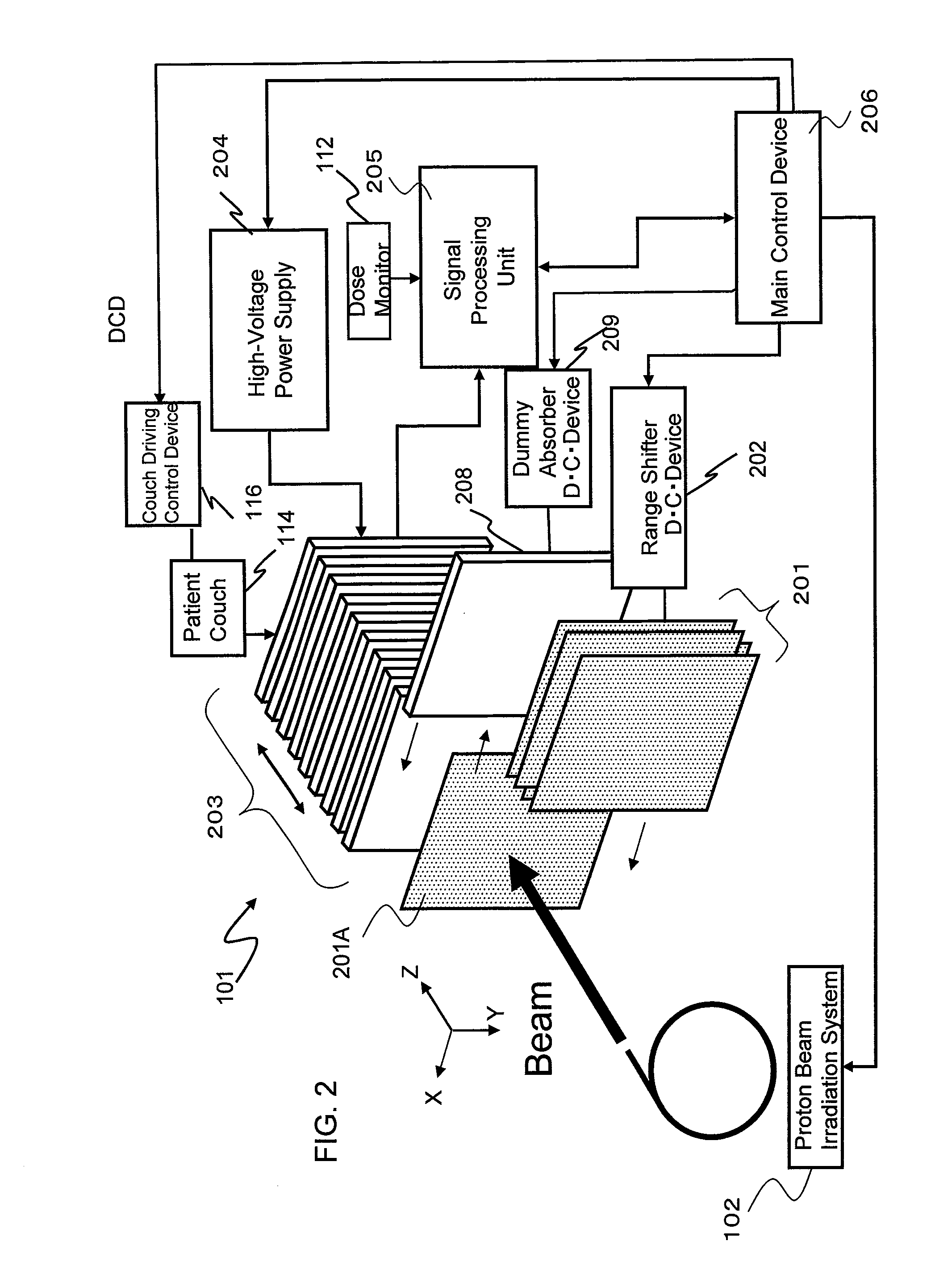
The present invention provides a calibration method for a stacked type of radiation detector. This method enables quick and easy correction of variations in sensor-specific output without using a water-phantom dose detector. The invention also includes a particle therapy system that utilizes the calibration method for the radiation detector.

Problems solved by technology

However, using a water-phantom dose detector to calibrate each stacked ionization chamber has required a great deal of labor and time.

Method used


Image

  • Calibration method for radiation detector, and particle therapy system
  • Calibration method for radiation detector, and particle therapy system
  • Calibration method for radiation detector, and particle therapy system

Examples


Embodiment Construction

[0019]Particle therapy systems that employ the scanning method are adjusted to within scan position errors of ±1 mm so that the system scans a beam laterally across an indicated position. These systems are also adjusted to within beam range errors of ±1 mm to ensure that the beam reaches an indicated depth level. The range denotes a maximum depth that the beam can reach when it travels through the medium, and this value depends upon incident energy of the beam.

[0020]To confirm adjustment results on the particle therapy system, a radiation detector measures the scanning position and Bragg curve of the beam. The Bragg curve is a distribution of linear energy transfer (LET) in the depth direction, expressed in terms of [J / m], and depends upon the incident energy of the beam. More specifically, LET is the energy that the particle beam passing through the medium transfers thereto while traveling through a unit distance in the depth direction. The beam's reachable depth is calculated from...


PUM


Abstract

A stacked type of radiation detector and a calibration method that enables the radiation detector to correct variations in sensor-specific output easily and within a short time, without using a water-phantom dose detector. The radiation detector is equipped with a sensor section including a plurality of sensors arranged in layers in a traveling direction of a particle beam. A dummy absorber has water-equivalent thickness equal to an average water-equivalent thickness of the sensors. A signal-processing unit calculates sensor-specific calibration coefficients using a measurement result obtained during irradiation of the radiation detector with the radiation when electrical signals developed in each sensor are measured, and a measurement result obtained during irradiation of the radiation detector with the radiation when the sensor section is moved in the traveling direction of the radiation, then the dummy absorber is set in place, and electrical signals developed in each sensor are measured.

Description

BACKGROUND OF THE INVENTION[0001]1. Field of the Invention[0002]The present invention relates to a method for calibrating a radiation detector, and to a particle therapy system.[0003]2. Description of the Related Art[0004]A scanning method is becoming widespread in particle therapy. The scanning method is a technique used to divide a target region into very small segments, called spots, and irradiate each spot independently with a narrow beam having a small diameter of 1σ=3 to 20 mm. The irradiation is stopped once a predetermined dose has been delivered to the spot, and after that, a next spot is scanned with the same beam. Scanning magnets are used when the beam is to be scanned in a direction perpendicular to a direction in which the beam travels (hereinafter, this scanning direction is referred to as the lateral direction, and likewise the traveling direction of the beam, as the depth direction). After the predetermined dose has been delivered to a certain depth in all spots, th...

Claims


Application Information

Patent Timeline
IPC IPC(8): G01T7/00
CPCA61N5/1048G01T1/29A61N2005/1087A61N5/1075G01T7/005
Inventor TAKAYANAGI, TAISUKENISHIUCHI, HIDEAKITADOKORO, MASAHIROFUJII, YUSUKESAKAE, TAKEJITERUNUMA, TOSHIYUKI
Owner HITACHI LTD
Learn More