
Single-phase induction motor and method for reducing noise in the same

a single-phase induction motor and noise reduction technology, applied in the direction of motor/generator/converter stopper, dynamo-electric gear control, motor/generator/converter stopper, etc., can solve the problems of noise and vibration, noise and vibration in the motor, vibration and noise in the actual operation of the motor, etc., to reduce noise, low noise, and low vibration motor

Active Publication Date: 2007-07-17
SAMSUNG ELECTRONICS CO LTD
View PDF60 Cites 35 Cited by
  • Summary
  • Abstract
  • Description
  • Claims
  • Application Information

AI Technical Summary

Benefits of technology

The invention provides a method and system for reducing noise in a single-phase induction motor. The method involves controlling the phase difference between the main-winding and auxiliary-winding currents in the motor so that the magnetomotive forces of the stator windings are balanced, resulting in a low noise, low vibration motor. The control operation can be based on the ratio of the auxiliary-winding magnetomotive force to the main-winding magnetomotive force or the backward magnetomotive force. The technical effects of the invention include reduced noise and vibration, improved motor performance, and improved user experience.

Problems solved by technology

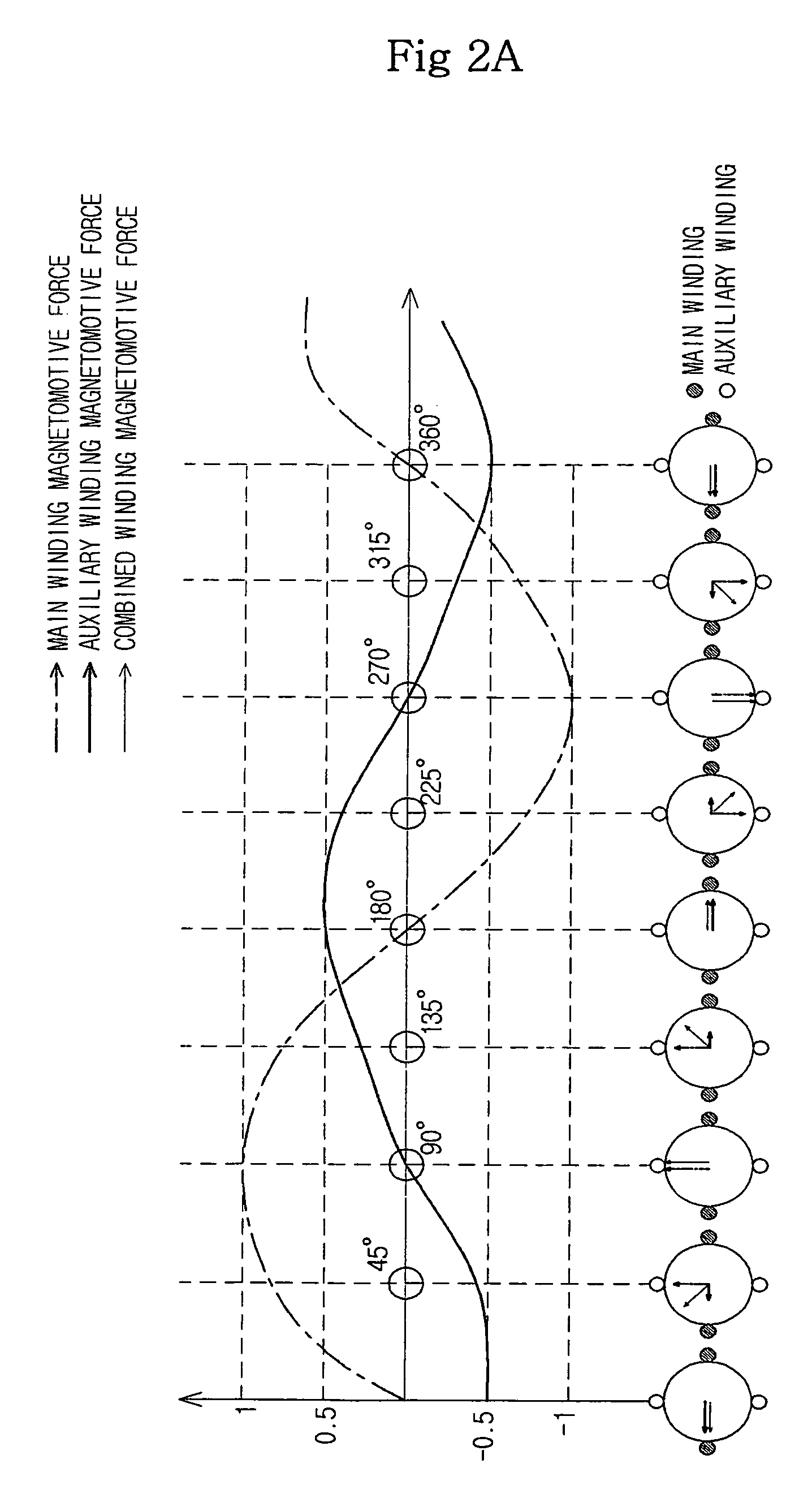
If a ripple is present in the rotating magnetomotive force, torque ripple occurs in the rotor, causing noise and vibration in the motor.
In this conventional motor, even if phase equilibrium is established in a certain running range of the motor, the phase equilibrium is broken causing noise and vibration if a tap in the stator windings is switched to select a different running range.
In addition, even if phase equilibrium is established under a condition where no load is present, the phase equilibrium is broken under a condition where a load is present, due to characteristics of the single-phase induction motor, so that vibration and noise occurs in actual operation of the motor.

Method used


Image

  • Single-phase induction motor and method for reducing noise in the same
  • Single-phase induction motor and method for reducing noise in the same
  • Single-phase induction motor and method for reducing noise in the same

Examples


Embodiment Construction

[0034]Reference will now be made in detail to the embodiments of the present invention, examples of which are illustrated in the accompanying drawings, wherein like reference numerals refer to the like elements throughout. The embodiments are described below to explain the present invention by referring to the figures.

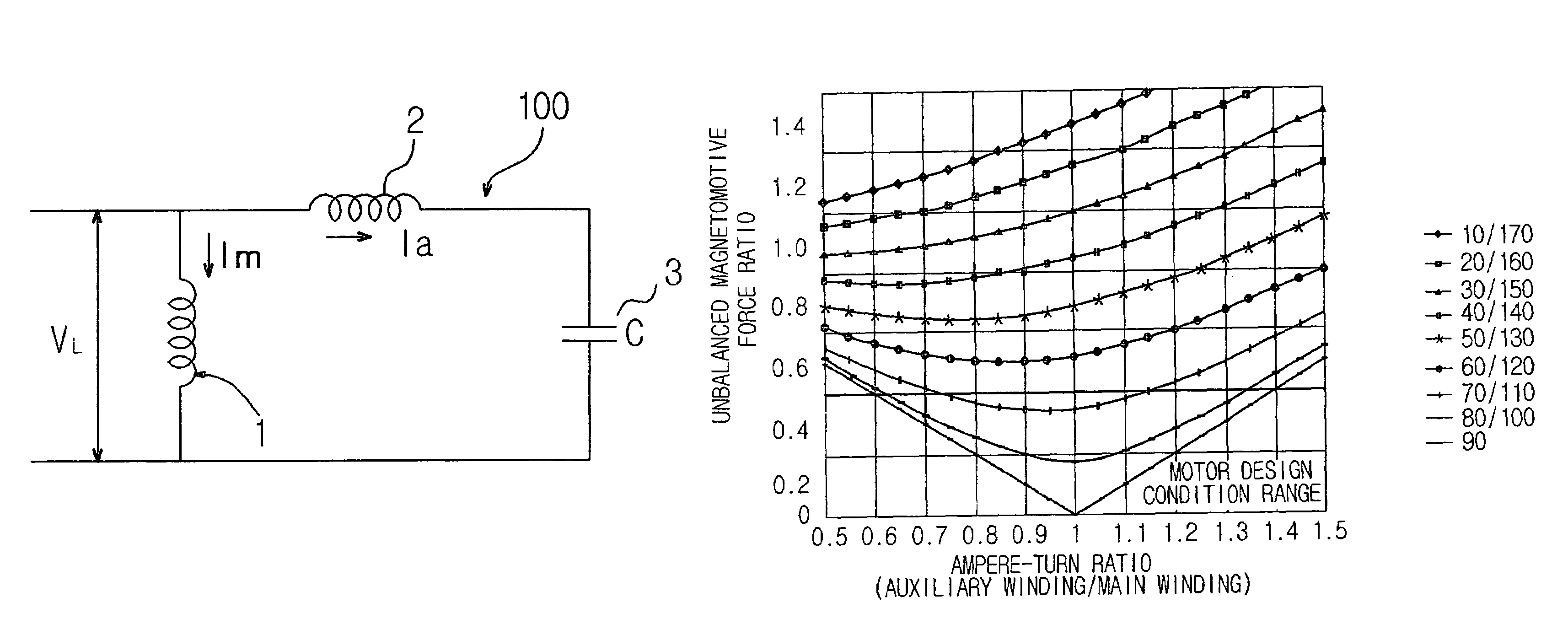
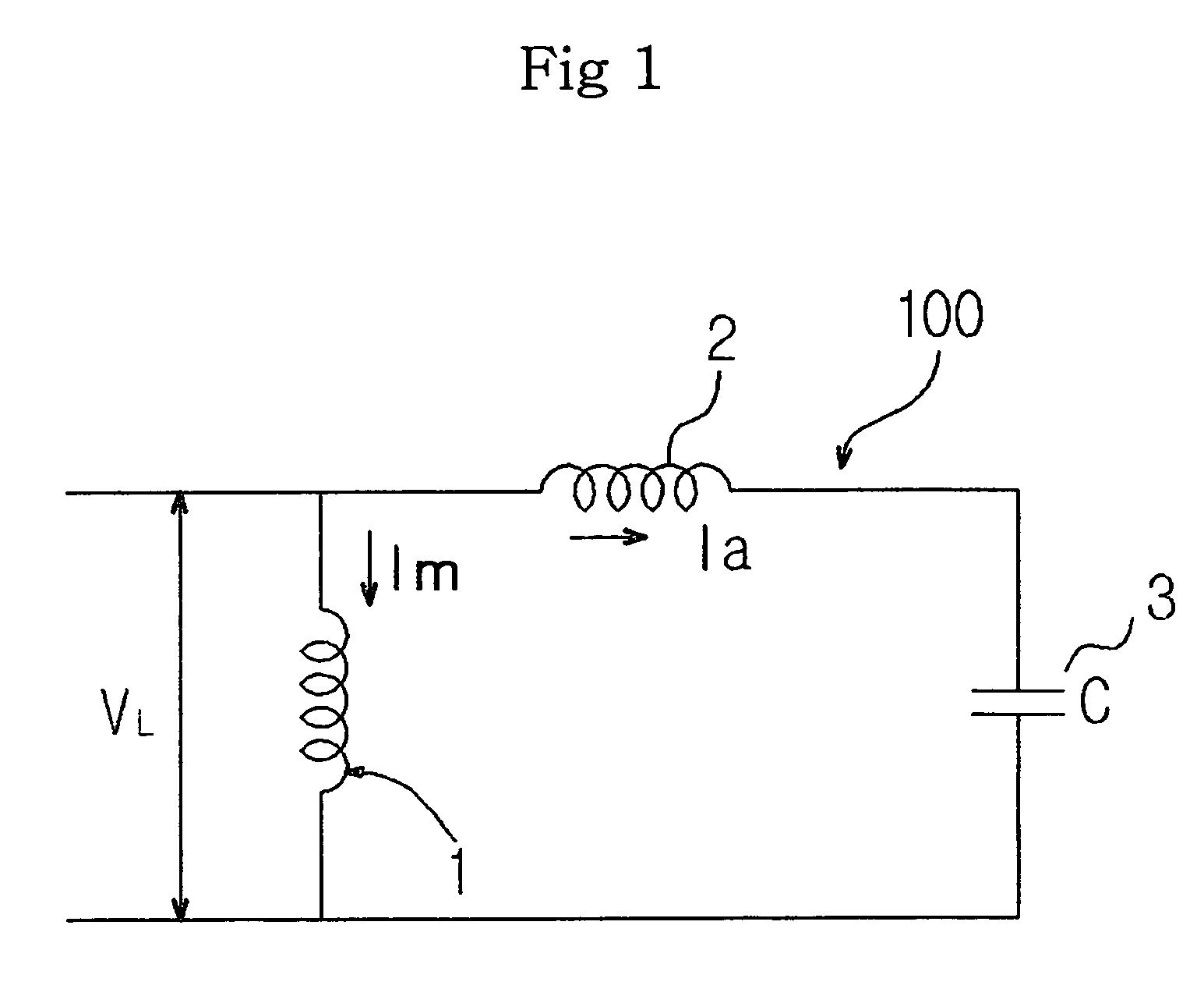
[0035]As shown in FIG. 1, the single-phase induction motor 100 according to the present invention is a capacitor-run motor in which a power source VL is connected to a main winding 1, an auxiliary winding 2 is connected in parallel to the main winding 1, and a capacitor 3 is connected in series to the auxiliary winding 2. Current flowing through the main and auxiliary windings 1 and 2 when the single-phase induction motor 100 starts producing magnetic fields inside the motor 100. The magnetic field produced by the main winding 1 induces a current in a rotor (not shown). The induced current produces another magnetic field in the rotor. A rotating magnetic field generate...


PUM


Abstract

A single-phase induction motor and a method for reducing noise in the same, which can eliminate unbalance between magnetomotive forces of main and auxiliary windings in a stator of the motor, thereby implementing a low noise, low vibration motor, and can also achieve balance between the magnetomotive forces of the stator windings in the entire running range of the motor, and can further achieve balance between the magnetomotive forces of the stator windings on the basis of temperature increase of the motor as it runs. The amplitude of a main-winding current flowing through the main winding in the stator is controlled to be equal to the amplitude of an auxiliary-winding current flowing through the auxiliary winding in the stator, and the phase difference between the main-winding and auxiliary-winding currents is controlled to be maintained at a predetermined value.

Description

CROSS-REFERENCE TO RELATED APPLICATIONS[0001]This application claims the benefit of Korean Patent Application No. 10-2004-0094349, filed on Nov. 17, 2004 in the Korean Intellectual Property Office, the disclosure of which is incorporated herein by reference.BACKGROUND OF THE INVENTION[0002]1. Field of the Invention[0003]The present invention relates to single-phase induction motors, and more particularly, to a single-phase induction motor and a method for reducing noise in the same, which minimize noise and vibration by balancing the magnetomotive forces of stator windings in the motor.[0004]2. Description of the Related Art[0005]A single-phase induction motor is a type of alternating current “AC” motor. The simplest configuration of the single-phase induction motor uses commercial power without alteration and includes a single-phase main winding provided in a stator and a squirrel-cage shaped conductor provided in a rotor. Since the motor is not rotated with commercial power alone,...

Claims


Application Information

Patent Timeline
Patent Type & Authority Patents(United States)
IPC IPC(8): H02P23/00H02K17/08H02P21/05H02P23/04H02P23/07H02P25/04H02P27/06
CPCH02P25/04H02K17/08H02P1/44
Inventor JOO, JAE MANLEE, JUN HWAHONG, SEUNG GEE
Owner SAMSUNG ELECTRONICS CO LTD
Learn More