
Power transmission device, electric power steering device, and method of producing the same

a technology of transmission device and electric steering device, which is applied in the direction of mechanical equipment, transportation and packaging, and packaging, and achieves the effects of eliminating the need for disassembly, high reliability and high reliability

Active Publication Date: 2007-07-17
KYB CORP
View PDF21 Cites 26 Cited by
  • Summary
  • Abstract
  • Description
  • Claims
  • Application Information

AI Technical Summary

Benefits of technology

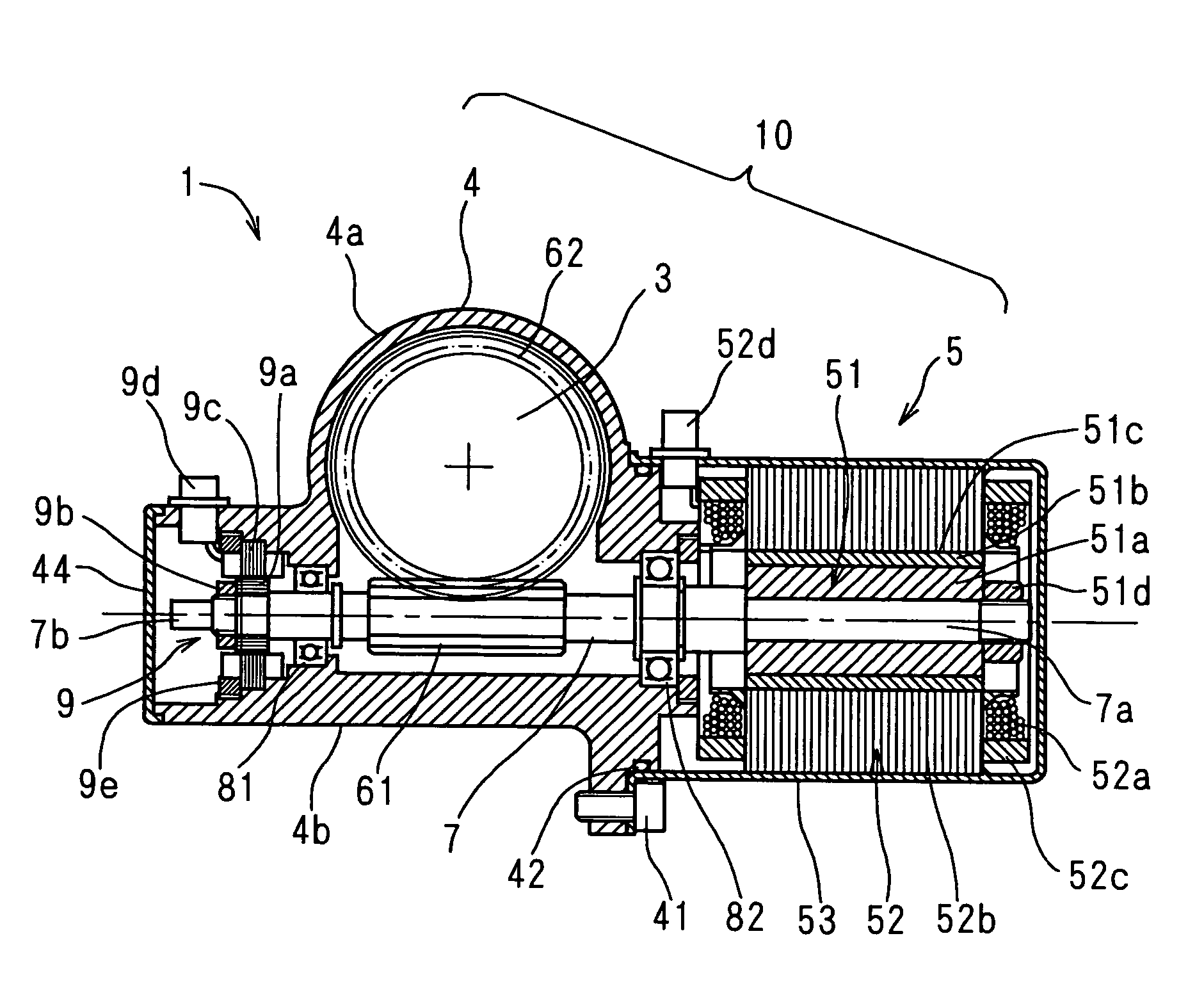
[0008]The present invention employs the motor section comprising the rotational shaft, the rotor fixed on the inner end side of the rotational shaft, and the stator positioned opposite to the rotor. A motor as a completed product is not used. Therefore, while the conventional art needs to connect the output shaft of the motor and the rotational shaft having the driving gear fixed thereon by spline machining and so on, the present invention only requires a single rotational shaft. Thus, it is not necessary to connect shafts by using spline machining and so on. It is therefore possible to reduce the number of components and the manufacturing cost. Moreover, since only the single rotational shaft is necessary, only the two bearings are required. As a result, the number of components and the manufacturing cost can be reduced and the device can have a smaller size and a lighter weight. Additionally, since the shafts are not connected using spline machining, problems caused by rattling resulting from spline grooves on a connected part, for example, unusual noise and a reduction in response of a worm gear to the rotation of the motor, do not occur. Further, as the number of bearings is smaller, force required for rotating the steering shaft is reduced, thereby improving the steering feel. Furthermore, since the rotational shaft is supported by the two bearings on both sides of the driving gear, even when the bearings are displaced, it is possible to minimize the inclination of the rotational shaft. Therefore, the efficiency of transmitting power from the driving gear to the driven gear does not decrease.
[0011]Therefore, in a state in which the rotational shaft assembling step is performed, the first bearing and the second bearing for supporting the rotational shaft have already been fixed on the common fixed-side member, thereby accurately performing a step of inspecting engagement. Further, since the step of inspecting engagement can be performed before the rotor assembling step, if a problem occurs with the driving gear or the driven gear, a gear having a problem can be replaced easily. Particularly, when the power transmission device is used for the electric power steering device, a worm wheel gear attached to the side of the steering shaft is used as the driven gear and a worm gear is used as the driving gear. In this case, since engagement requires high accuracy, it is more likely that gears will exhibit problems. However, according to the present invention, the worm wheel gear or the worm gear can be replaced easily, thereby readily solving a problem in engagement. Further, in the case of the electric power steering device, even if a problem is found with the worm wheel gear or the worm gear after the device is assembled, disassembly cannot be performed easily. However, in the present invention, the step of inspecting engagement is performed and a problem with engagement can be solved before the rotor assembling step, so that the electric power steering device can be improved in yield.
[0013]Additionally, when the motor has a brushless structure, a movable member for detecting rotation is mounted on the distal end side from the first bearing on the rotational shaft, and a detector for detecting the rotation of the movable member for detecting rotation is attached to the fixed-side member. In such a configuration, according to the present invention, after the stator assembling step, while a movable member of a rotation detecting device is assembled to the distal end side from the first bearing on the rotational shaft, the detector for detecting the rotation of the movable member is attached to the fixed-side member. In this state, the step of assembling the rotation detecting device can be performed to adjust a phase of the rotation detecting device. When the position is adjusted at such a time, since the inspections of the engaged part and the motor section have been completed in the previous step, problems with the engaged part and the motor section are not found after the position is adjusted. For this reason, it is possible to eliminate the necessity for disassembling in the event of a problem after assembling has been performed.
[0014]Such a power transmission device can be used, for example, for an electric power steering device. In this case, the driven gear is a worm wheel gear attached to the side of the steering shaft, the driving gear is a worm gear engaged with the worm wheel gear, and the motor section is used for assisting steering drive, the motor assisting the rotation of the steering shaft by driving to rotate the worm wheel gear via the worm gear. With such a device, particularly high reliability is required. According to the present invention, it is possible to perform inspections at the most appropriate timing according to the progress of the assembly, thereby manufacturing an electric power steering device with high reliability.

Problems solved by technology

Additionally, since the shafts are not connected using spline machining, problems caused by rattling resulting from spline grooves on a connected part, for example, unusual noise and a reduction in response of a worm gear to the rotation of the motor, do not occur.

Method used


Image

  • Power transmission device, electric power steering device, and method of producing the same
  • Power transmission device, electric power steering device, and method of producing the same
  • Power transmission device, electric power steering device, and method of producing the same

Examples


Embodiment Construction

[0025]An example of an electric power steering device according to the present invention and a method of manufacturing the same will be described with reference to the drawings.

(Electric Power Steering Device)

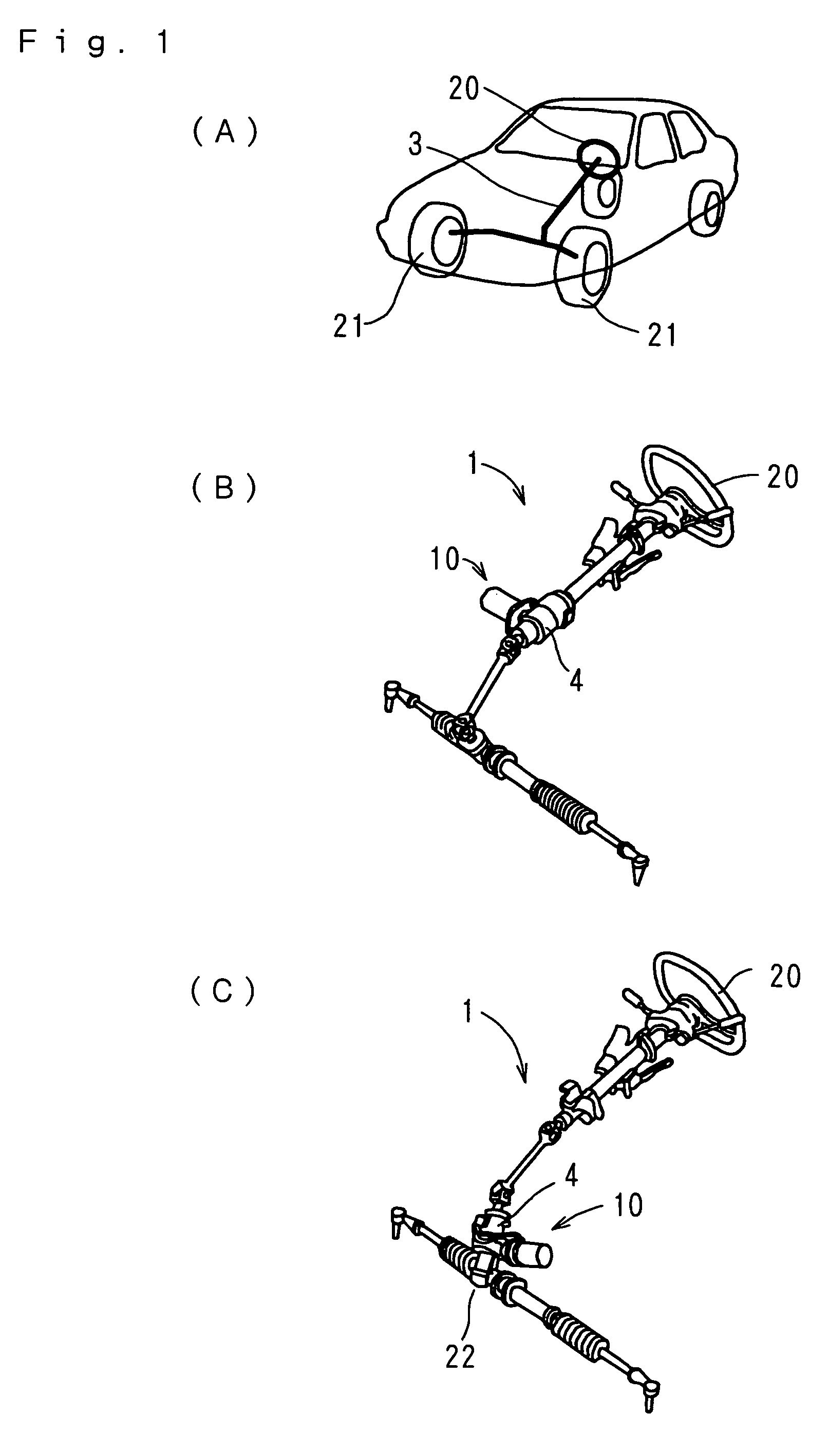
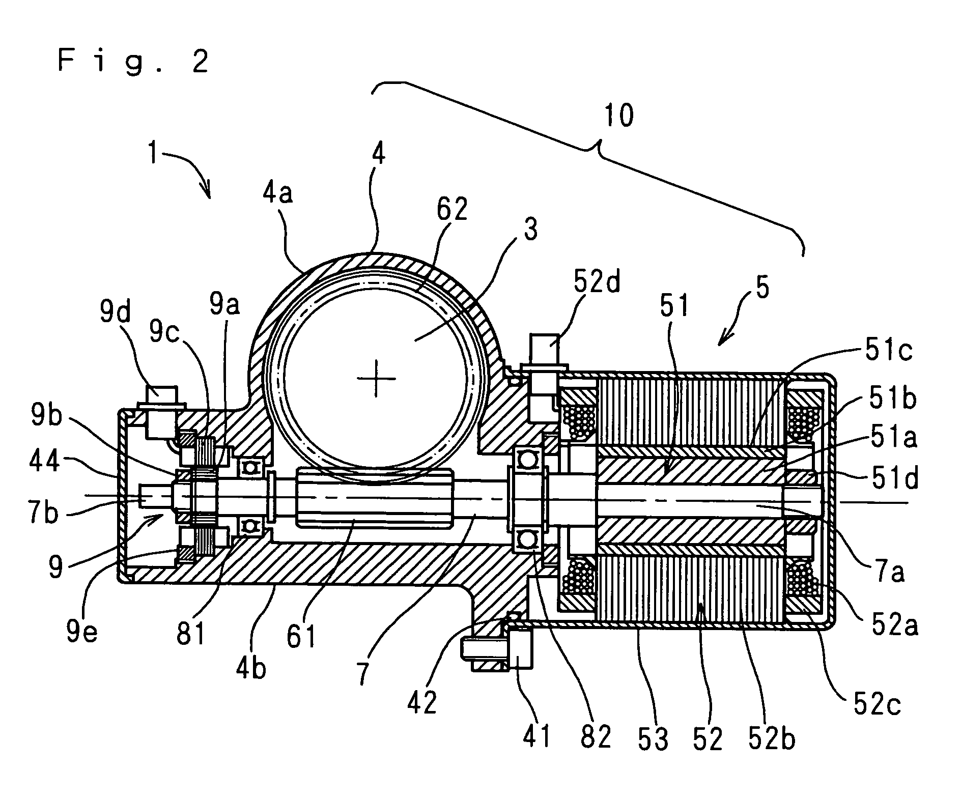
[0026]FIGS. 1(A), 1(B), and 1(C) are explanatory views of the electric power steering device employing the present invention. FIG. 2 is a sectional view showing a power transmission device used for the electric power steering device of the present invention.

[0027]As shown in FIG. 1(A), with respect to the steering of an automobile, an operation of a steering wheel 20 is transmitted to wheels 21 via a steering shaft 3. In recent years, in order to assist the operation, a power transmission device 10 having a reduction device and an auxiliary motor, which will be discussed later, have been provided in a steering column just like an electric power steering device 1 shown in FIG. 1(B). Further, like an electric power steering device 1 of FIG. 1(C), a power transmission device 10 ha...


PUM


Abstract

In order to achieve low cost, small size, and light weight, to improve response at the time of transmission of power, and to prevent the occurrence of unusual noise, a power transmission device (10) of an electric power steering device (1) has a motor section (5) comprising a rotational shaft (7), a rotor (51) attached to an inner end side (7a) of the rotational shaft (7), and a stator (52) positioned opposite to the rotor (51), a worm gear (61) attached to a distal end side (7b) from the motor section (5) on the rotational shaft (7), and a worm wheel gear (62) engaged with the gear (61). The rotational shaft (7) is rotatably supported by first and second bearings (81, 82), the first bearing (81) being held by a housing (4) at a distal end side (7b) to the worm gear (61). The second bearing (82) is held by the housing (4) between the worm gear (61) and the rotor (51) so that the worm gear (61) is sandwiched between the first and second bearings (81, 82).

Description

TECHNICAL FIELD[0001]The present invention relates to a power transmission device for transmitting rotary driving force of a motor via gears, an electric power steering device having the power transmission device used for assisting steering drive, and a method of manufacturing these devices.BACKGROUND ART[0002]When a steering wheel of an automobile is operated, a steering shaft is rotated, and rotation of this steering shaft is converted to a reciprocating motion and changes the directions of wheels. An electric power steering device for assisting such a steering operation by using driving force of a motor is disclosed in, for example, JP-A 2001-206230.[0003]In such an electric power steering device, as shown in FIG. 7, a reduction device for transmitting the rotary driving force of a motor has a motor 5A, a rotational shaft 7B connected to an output shaft 7A of the motor 5A via a coupling sleeve 8A, a worm gear 61 fixed on the rotational shaft 7B, and a worm wheel gear 62 engaged w...

Claims


Application Information

Patent Timeline
Patent Type & Authority Patents(United States)
IPC IPC(8): F16H35/00B62D5/04B62D15/02F16H1/16H02K7/08H02K7/10H02K7/116H02K29/06
CPCB62D5/0403B62D5/0409B62D15/0235H02K7/081H02K7/1166Y10T74/19684Y10T74/19828F16H1/16
Inventor TAKAHASHI, MASASHINARUSE, NOBUHARU
Owner KYB CORP
Learn More