
OFDM signal communication system, OFDM signal transmitting device and OFDM signal receiving device

a signal communication system and signal technology, applied in the field of orthogonal frequency division multiplexing (ofdm) signal communication system, can solve the problems of difficult realization of conventional transmitter-receiver in the mimo channel, extremely large signal processing capability, and difficulty in realizing effective equalizer, so as to reduce power consumption, increase the hardware size of the device, and increase the power consumption

Active Publication Date: 2007-07-10
NIPPON TELEGRAPH & TELEPHONE CORP
View PDF13 Cites 121 Cited by
  • Summary
  • Abstract
  • Description
  • Claims
  • Application Information

AI Technical Summary

Benefits of technology

[0031]Consequently, since interference cancellation is performed for each of the subcarriers, simple and highly accurate interference cancellation is possible. Furthermore, according to this OFDM signal communication system, since feed forward processing is possible without the need to perform feedback control as with the case where the equalizer is used, stable operation can be achieved even under a severe frequency selective fading environment.
[0033]However, for the inverse matrix computer and the interference canceller, since the processing is complicated, if both these functions are provided, the hardware size of the device is increased, and the power consumption is also increased. Consequently, it is not desirable to mount the inverse matrix computer and the interference canceller on a mobile terminal.
[0034]In view of the above, in the case where it is assumed that at least one of the inverse matrix computer and the interference canceller is mounted on the OFDM signal transmitting device side, then for example, for the OFDM signal transmitting device, it may be considered to associate this with the base station for controlling a plurality of mobile terminals, and for OFDM signal receiving device it may be considered to associate this with respective mobile terminals. By so doing, problems associated with miniaturization of the mobile terminal, or reduction in the power consumption can be overcome.

Problems solved by technology

Furthermore, in the case where broadband transmission is performed in a severe multipath fading environment, frequency selective fading occurs, so that it is necessary to accurately identify the frequency characteristics for the amplitude and phase which are generated by the fading, in an extremely short time for each of the systems.
However, in the current fading environment, the number and strength of the incoming delayed waves, and the so called delay profiles are diverse, and for all of these environments, realization of an effective equalizer is extremely difficult.
Therefore, although the transmitter-receiver in the MIMO channel can be realized under an environment close to the Additive White Gaussian Noise channel such as for point-to-point communication, in a MIMO channel in severe multipath fading environments, an extremely large signal processing capability is necessary.
Therefore realization of a conventional transmitter-receiver in the MIMO channel is difficult.
This is because, in the case where equalizing accuracy cannot be achieved, the interference cancellation is not sufficient, resulting in residual interference noise.
However, with the equalizer, since high accuracy equalization for the frequency characteristics of the amplitude and phase is difficult, there is a problem in that the signal-to-interference noise ratio easily deteriorates.
Furthermore, in the case where a wireless communication system is assumed between a fixed based station and a mobile terminal, if complicated processing functions are provided in the mobile terminal side, a problem arises from the point of miniaturization and low cost for the mobile terminal due to increase in hardware size and increase in power consumption.

Method used


Image

  • OFDM signal communication system, OFDM signal transmitting device and OFDM signal receiving device
  • OFDM signal communication system, OFDM signal transmitting device and OFDM signal receiving device
  • OFDM signal communication system, OFDM signal transmitting device and OFDM signal receiving device

Examples


first embodiment

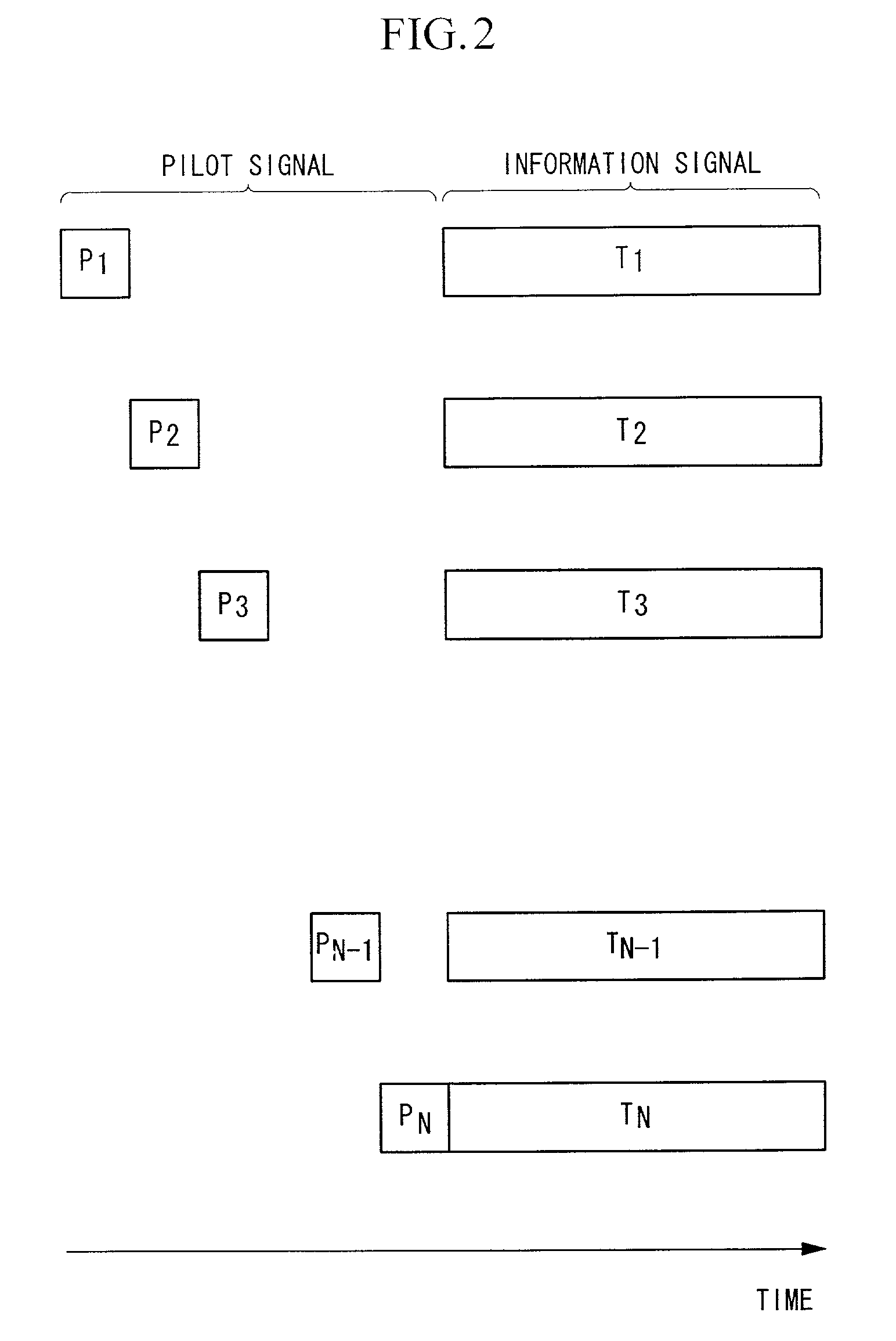
[0074]A block diagram of an OFDM signal communication system according to a first embodiment is shown in FIG. 1. In this embodiment, the OFDM signal communication system comprises N OFDM signal transmitting device which use the same radio frequency, equipped with two or more N transmitting antennas and connected to each of the antennas, and N OFDM signal receiving device which use the same radio frequency, furnished with N receiving antennas and connected to each of the antennas.

[0075]The construction and operation of the preferred embodiment of FIG. 1 will be described in detail. In this embodiment, N OFDM modulators 1-1 to 1-N are arranged corresponding to N transmitting antennas 5-1 to 5-N. In the OFDM modulators 1-1 to 1-N modulation of the subcarrier and inverse Fourier transformation is performed. To these OFDM modulators 1-1 to 1-N, common OFDM symbol timing is supplied from an OFDM symbol timing control circuit 2.

[0076]Transmission information signals T1 to TN are combined o...

second embodiment

[0111]Next is a description of a second embodiment of the present invention using FIG. 3. In order to improve the performance under fading, in general, OFDM is used combining forward error correction and interleaving. An embodiment with forward error correction and interleaving combined is shown in FIG. 3.

[0112]In FIG. 3, the transmission information signals T1 to TN are subjected to be encoded for forward error correction in forward error correction encoders 15-1 to 15-N, and are then subjected to be interleaved in interleavers 16-1 to 16-N in the subcarrier domain, that is in the frequency domain. This is performed in order to avoid successive errors due to depression of the level (notching) in a certain frequency neighborhood, and obtain large performance improvement by forward error correction.

[0113]In the receiver, the demodulation output is subjected to be deinterleaved, as a reverse operation to the interleaving of the transmitter, in deinterleavers 17-1 to 17-N, and is then ...

third embodiment

[0115]In the construction of FIG. 3, in the case of comparatively long delay fading (refer to FIG. 4B), successive errors do not occur and hence satisfactory characteristics are obtained. However in the case of short delay fading, the fading period on the frequency domain is long as shown in FIG. 4A, and hence the notch becomes wide, and in this part, successive errors are likely to occur, and forward error correction gain is small.

[0116]The third embodiment of the present invention will be explained with reference to FIG. 5. This embodiment is an embodiment for improving the lowering of the forward error correction gain as described above.

[0117]The transmission information signals T1 to TN are subjected to be encoded for error correction encoding in the forward error correction encoders 15-1 to 15-N as shown in FIG. 5, and are then interleaved both in the subcarrier domain (frequency domain) and in the transmitting antenna domain (space domain) in the interleaver 16, to thereby aff...


PUM


Abstract

An OFDM signal communication system used in broadband mobile communication, achieves stable operation under severe frequency selective fading environments, giving high quality. The OFDM signal communication system which transmits OFDM signals over the same radio frequency from N transmitting antennas, has an inverse matrix computer for computing an N×N inverse matrix constituted by propagation coefficients for respective propagation paths between each of N transmitting antennas and each of N receiving antennas, and a subcarrier demodulator which separates the signals of the respective propagation paths, based on the obtained inverse matrix.

Description

BACKGROUND OF THE INVENTION[0001]1. Field of the Invention[0002]The present invention relates to an orthogonal frequency division multiplexing (OFDM) signal communication system used in broadband mobile communication and the like, which divides transmission signals into subcarrier groups orthogonal to each other to perform multi-carrier transmission. More specifically, the invention relates to an OFDM signal communication system which achieves substantial frequency utilization efficiency under a multipath fading environment, using a plurality of transmitting antennas and a plurality of receiving antennas, and which uses a space division multiplexing (SDM) method or polarization division multiplexing (PDM) that can achieve signal transmission with high quality, high capacity, and high speed.[0003]2. Description of the Related Art[0004]For example in broadband mobile communication, since the frequency band which can be used is limited, then in order to deal with full-scale multi-media...

Claims


Application Information

Patent Timeline
IPC IPC(8): H04K1/10H04B7/02H04J11/00H04L1/06H04L27/00H04L27/26
CPCH04L1/06H04L27/2657H04L27/2662H04L27/2679H04L27/2602H04L2027/0026H04L2027/0087H04L27/2637H04L27/26035H04L27/265H04L27/2688
Inventor SUGIYAMA, TAKATOSHIASAI, YUSUKEKUROSAKI, SATOSHIUMEHIRA, MASAHIROUCHIDA, DAISEISUZUKI, YASUO
Owner NIPPON TELEGRAPH & TELEPHONE CORP
Learn More